Ohm`s Law
advertisement

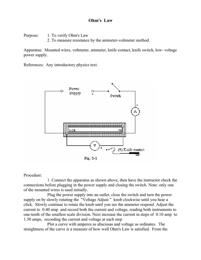
Ohm's Law Purpose: 1. To verify Ohm's Law 2. To measure resistance by the ammeter-voltmeter method. Apparatus: Mounted wires, voltmeter, ammeter, knife contact, knife switch, low- voltage power supply. References: Any introductory physics text. Procedure: 1. Connect the apparatus as shown above, then have the instructor check the connections before plugging in the power supply and closing the switch. Note: only one of the mounted wires is used initially. Plug the power supply into an outlet, close the switch and turn the power supply on by slowly rotating the "Voltage Adjust " knob clockwise until you hear a click. Slowly continue to rotate the knob until you see the ammeter respond. Adjust the current to 0.40 amp and record both the current and voltage, reading both instruments to one-tenth of the smallest scale division. Next increase the current in steps of 0.10 amp to 1.50 amps, recording the current and voltage at each step. Plot a curve with amperes as abscissas and voltage as ordinates. The straightness of the curve is a measure of how well Ohm's Law is satisfied. From the readings obtained at 0.50, 1.00 and 1.50 amps, compute the average resistance of the wire. 2. Change the connections to the other wire. Using currents of 0.50, 1.00 and 1.50 amps only, determine the average resistance of this wire. 3. Connect both wires in parallel (ask your instructor to check the connections before closing the switch) and determine their effective resistance at the same three values of current used in part 2. 4. Connect both wires in series (ask your instructor to check the connections before closing the switch) and determine their effective resistance at the same three values of current. Be aware that in this case the voltmeter must be connected across the two wires in series. 5. With the same connections as in (4) set the "Voltage Adjust " knob so that one of the meters reads full scale. Open the knife switch and replace the lead from the positive terminal of the voltmeter with the lead to the knife contact. With the knife contact, measure the potential difference or "potential drop" across 10 cm of wire. Repeat for 20, 30, 40 cm, etc. up to the full length of both wires with an additional reading at 75 cm. Record the ammeter reading in each case. Calculations: 1. From the results of procedures (1) and (2) compute the series and parallel resistance of the wires and compare the results with the measured values obtained in procedures (3) and (4). 2. Plot a curve of your data obtained in procedure (5), with computed resistances as ordinate and length in centimeters as abscissa. From this graph, compare the resistance of the full length of each wire to the results obtained in procedures (1) and (2). Note: In the voltmeter-ammeter method of measuring resistance (connections as in Fig. 5-1) it is assumed that the resistance of the voltmeter is large compared to that of the wire. The resistance of the voltmeter provided is sufficiently large that no corrections for it need be made in this experiment. Questions to be Answered in the Report: 1. If one lamp of a group of five identical lamps in series is removed, the voltage across the empty socket becomes equal to the line voltage, rather than remaining one-fifth of it. Why ? 2. The circuits, P and Q, show two different ammeter-voltmeter methods of measuring resistance. Suppose the ammeter has a resistance of 0.10 ohms and the voltmeter has a resistance of 3.0 ohms; the ammeter reads 2.5 amps and the voltmeter reads 6.0 volts. What is the uncorrected value of the resistance in each case? What is the true value of the resistance in each case? 3. A piece of copper wire of resistance R is cut into 10 equal lengths. These parts are connected in parallel. How does the joint resistance of the parallel combination compare with the original resistance of the single wire ?


