Recitation Week 9
advertisement

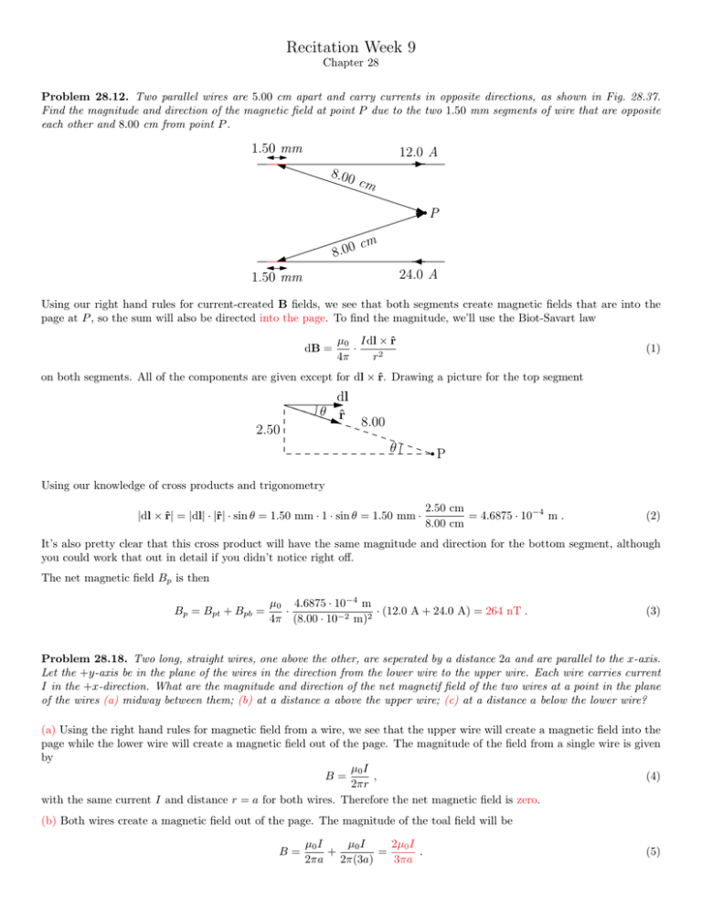
Recitation Week 9 Chapter 28 Problem 28.12. Two parallel wires are 5.00 cm apart and carry currents in opposite directions, as shown in Fig. 28.37. Find the magnitude and direction of the magnetic field at point P due to the two 1.50 mm segments of wire that are opposite each other and 8.00 cm from point P . 1.50 mm 12.0 A 8.00 cm P 8.00 cm 24.0 A 1.50 mm Using our right hand rules for current-created B fields, we see that both segments create magnetic fields that are into the page at P , so the sum will also be directed into the page. To find the magnitude, we’ll use the Biot-Savart law dB = µ0 Idl × r̂ · 4π r2 (1) on both segments. All of the components are given except for dl × r̂. Drawing a picture for the top segment dl θ r̂ 2.50 8.00 θ P Using our knowledge of cross products and trigonometry |dl × r̂| = |dl| · |r̂| · sin θ = 1.50 mm · 1 · sin θ = 1.50 mm · 2.50 cm = 4.6875 · 10−4 m . 8.00 cm (2) It’s also pretty clear that this cross product will have the same magnitude and direction for the bottom segment, although you could work that out in detail if you didn’t notice right off. The net magnetic field Bp is then Bp = Bpt + Bpb = µ0 4.6875 · 10−4 m · · (12.0 A + 24.0 A) = 264 nT . 4π (8.00 · 10−2 m)2 (3) Problem 28.18. Two long, straight wires, one above the other, are seperated by a distance 2a and are parallel to the x-axis. Let the +y-axis be in the plane of the wires in the direction from the lower wire to the upper wire. Each wire carries current I in the +x-direction. What are the magnitude and direction of the net magnetif field of the two wires at a point in the plane of the wires (a) midway between them; (b) at a distance a above the upper wire; (c) at a distance a below the lower wire? (a) Using the right hand rules for magnetic field from a wire, we see that the upper wire will create a magnetic field into the page while the lower wire will create a magnetic field out of the page. The magnitude of the field from a single wire is given by µ0 I B= , (4) 2πr with the same current I and distance r = a for both wires. Therefore the net magnetic field is zero. (b) Both wires create a magnetic field out of the page. The magnitude of the toal field will be B= µ0 I 2µ0 I µ0 I + = . 2πa 2π(3a) 3πa (5) (c) Both wires create a magnetic field into the page. The magnitude of the toal field will be B= µ0 I µ0 I 2µ0 I + = , 2π(3a) 2πa 3πa (6) the same as the magnitude for (b). Problem 28.23. Four long, parallel power lines each carry 100 A currents. A cross-sectional diagram of these lines if a square, 20.0 cm on each side. For each of the three cases shown in Fig. 28.41, calculate the magnetic field at the center of the square. Note that the magnitude of magnetic field at the center of the square from any corner wire will be Bw = µ0 I , 2π √a2 (7) √ where a = 20.0 cm is the side length of the square, and r = a/ 2 = a cos(45◦ ) is the distance from the corner of the square to the center. Using our right-hand rules to determine the direction of the magnetic field from each wire (a) (b) (c) For both (a) and (b), the magnetic fields cancel out and the net magnetic field at the center of the square is zero. We can also see this by symmetry, without using the right-hand rule. The (a) configuration is symmetric to 90◦ rotations about the square center, so the magnetic field at the center must also be symmetric to 90◦ rotations about the square center. A vector with non-zero length is only symmetric to 360◦ rotations, so there cannot be any magnetic field in the center of (a). Similarly, the (b) configuration is symmetric to 180◦ rotations, so it cannot have magnetic field at the center. (c) is only symmetric to 360◦ rotations, so it can have a magnetic field at the center. The magnitude of the magnetic field for (c) is given by the sum of the horizontal components of the corner magnetic fields, since the vertical components cancel out. Bc = 4Bw cos(45◦ ) = 4 · µ0 I 1 2µ0 I . a · √ = √ 2π 2 πa 2 (8) I r Problem 28.30. Calculate the magnitude and direction of the magnetic field at point P due to the current in the semicircular section of wire shown in Fig. 28.46. ( Hint: Does the current in the long, straight section of the wire produce any field at P ?) I P The Biot-Savart law µ0 Idl × r̂ · (9) 4π r2 gives the magnetic field from an infinitesimal chunk of current. The straight sections of wire do not contribute any magnetic field at P , because |dl × r̂| = |dl| · |r̂| sin θ = 0 , (10) dB = since θ = 0◦ to the left and 180◦ to the right. For all portions of wire along the semicircle, θ = 90◦ , and dl ×r̂ points into the page. The net magnetic field at P is therefore Z Z Z µ0 I µ0 I µ0 I µ0 I µ0 Idl × r̂ ◦ · = · |dl| · |r̂| sin(90 ) = |dl| = · πr = . (11) B= 2 2 2 2 4π r 4π r 4πr 4πr 4r s s s R where s |dl| is just the length of the semicircle, which is half the 2πr circumference of the entire circle. Problem 28.60. Figure 28.54 shows an end view of two long, parallel wires perpendicular to the xy-plane, each carrying a current I but in opposite directions. (a) Copy the diagram, and draw vectors to show the B field of each wire and the net B field at a point P . (b) Derive the expression for the magnitude of B at any point on the x-axis in terms of the x-coordinate of the point. What is the direction of B? (c) Graph the magnitude of B at points on the x-axis. (d) At what value of x is the magnitude of B a maximum? (e) What is the magnitude of B when x a? (a) y a P x a x (b) The magnitude of magnetic field from each wire at P is µ0 I µ I √ 0 = . 2πr 2π x2 + a2 Bw = (12) The net magnetic field is the sum of the horizontal components, since the vertical components cancel. B = 2Bw cos θ = 2 · a µ0 Ia µ I √ 0 , ·√ = 2 2 2 2 π(x2 + a2 ) 2π x + a x +a (13) where cos θ = a/r comes from a r θ θ (c) B a −a x (d) The magnitude of B has a maximum at x = 0. (e) For x a, x2 + a2 ≈ x2 , so B= µ0 Ia µ0 Ia ≈ . 2 2 π(x + a ) πx2 (14) Problem 28.62. A pair of long, rigid metal rods, each of length L, lie parallel to each other on a perfectly smooth table. Their ends are connected by identical, very light conducting springs of force constant k (Fig. 28.55) and negligable unstretched length. If a current I runs through this circuit, the springs will stretch. At what seperation will the rods remain at rest? Assume that k is large enough so that the separation of the rods will be much less than L. L k k d In order for the rods to remain at rest, the net force on each rod must be zero. The only forces we need to consider are the spring forces Fs and magnetic forces FB . The only other possible force for this problem would be a gravitational force Fg = mg, but no mass m is given for the rods, so we must assume Fg is negligable. Because of Newton’s third law, we know that if the forces of the bottom rod on the top rod cancel, then the forces from the top rod on the bottom rod must also cancel, and we can restrict our force balancing to only the top rod. The spring force on the top rod is Fs = 2kd (15) downward, due to a kx force for each spring (left and right), with x = d because the unstetched length of the springs is negligable. The magnetic force on the top rod is FB = IL × B , (16) where B is the magnetic field along the top rod created by the current in the bottom rod. This magnetic field can be approximated as as that due to an infinitely long, straight wire a distance d below the top wire B= µ0 I 2πd (17) directed into the board. The bottom wire is not infinitely long, but because d L, fringe effects due to the wire’s finite length are small. Because the magnetic field is into the board and the current in the top wire is to the right, the vector FB is µ0 I 2 L (18) FB = |IL| · |B| sin θ = ILB = 2πd directed upward. Putting this all together to balance the forces on the top bar 0= X Fy = FB − Fs = µ0 I 2 L 2πd 2 µ 0I L d2 = r4πk µ0 L d= I. 4πk 2kd = µ0 I 2 L − 2kd 2πd (19) (20) (21) (22)


