P. LeClair
advertisement

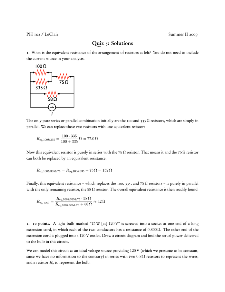
PH 102 / LeClair Summer II 2009 Quiz 5: Solutions 1. What is the equivalent resistance of the arrangement of resistors at left? You do not need to include the current source in your analysis. 100 Ω 75 Ω 335 Ω 58 Ω I The only pure series or parallel combination initially are the 100 and 335 Ω resistors, which are simply in parallel. We can replace these two resistors with one equivalent resistor: Req,100&335 = 100 · 335 Ω ≈ 77.0 Ω 100 + 335 Now this equivalent resistor is purely in series with the 75 Ω resistor. That means it and the 75 Ω resistor can both be replaced by an equivalent resistance: Req,100&335&75 = Req,100&335 + 75 Ω = 152 Ω Finally, this equivalent resistance – which replaces the 100, 335, and 75 Ω resistors – is purely in parallel with the only remaining resistor, the 58 Ω resistor. The overall equivalent resistance is then readily found: Req, total = Req,100&335&75 · 58 Ω ≈ 42 Ω Req,100&335&75 + 58 Ω 2. 10 points. A light bulb marked “75 W [at] 120 V” is screwed into a socket at one end of a long extension cord, in which each of the two conductors has a resistance of 0.800 Ω. The other end of the extension cord is plugged into a 120 V outlet. Draw a circuit diagram and find the actual power delivered to the bulb in this circuit. We can model this circuit as an ideal voltage source providing 120 V (which we presume to be constant, since we have no information to the contrary) in series with two 0.8 Ω resistors to represent the wires, and a resistor Rb to represent the bulb: Rb 0.8 0.8 - + ∆V = 120 Great, but what is the bulb resistance? The stated power (75 W) and voltage (120 V) let us determine the power, by noting that for a resistor power, voltage, and resistance are simply related: P= (∆V )2 Rb =⇒ Rb = 1202 [V]2 ≈ 192 Ω 75 [W] This is determined from the maximum rated power at the ideal voltage. In our actual circuit, the bulb does not “see” the whole 120 V, there must be some voltage drop across the 0.8 Ω resistors representing the cord. Since this is a simple series circuit, our total resistance is Req = 0.8 + 0.8 + 192 = 193.6 Ω, meaning the current in the circuit must be I = ∆V /Req = 120/193.6 ≈ 0.62 A. Now we can find the power delivered to the bulb in one of two ways: calculate the actual voltage drop across the bulb (120 volts minus the voltage drops of 0.8I across the wires) and use its resistance, or we can use the current through the bulb and its resistance. The second method is one less step: Pbulb = I 2 Rb ≈ 73.76 W ≈ 73.8 W We cannot just use the total voltage supplied and the bulb resistance, as that would not take into account the voltage (and therefore power) lost in the wires. Similarly, we cannot use the total voltage and equivalent resistance, since that would also count the power dissipated in the wires. We must use either the actual voltage drop on the bulb or the current flowing through it (or both) to find the actual power delivered to the bulb.


