Introduction to Feedback
advertisement

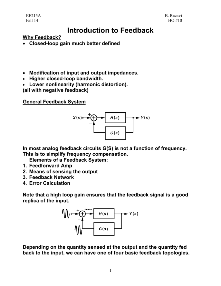
EE215A Fall 14 B. Razavi HO #10 Introduction to Feedback Why Feedback? Closed-loop gain much better defined Modification of input and output impedances. Higher closed-loop bandwidth. Lower nonlinearity (harmonic distortion). (all with negative feedback) General Feedback System In most analog feedback circuits G(S) is not a function of frequency. This is to simplify frequency compensation. Elements of a Feedback System: 1. Feedforward Amp 2. Means of sensing the output 3. Feedback Network 4. Error Calculation Note that a high loop gain ensures that the feedback signal is a good replica of the input. Depending on the quantity sensed at the output and the quantity fed back to the input, we can have one of four basic feedback topologies. 1 EE215A Fall 14 B. Razavi HO #10 Properties of Negative Feedback 1. Gain Desensitization Loop Gain: Example: 2. I/O Impedance Modification 2 EE215A Fall 14 B. Razavi HO #10 Another Example: 3. Bandwidth Modification If the unity-gain bandwidth doesn’t change, why use feedback at all? 3 EE215A Fall 14 B. Razavi HO #10 4. Nonlinearity Reduction Since feedback makes the open-loop gain relatively independent of the open-loop gain, the variation of the open-loop gain with signal level affects the closed-loop behavior to a lesser extent. Types of Amplifiers Ideal Models: Examples: How do we improve these circuits? Sense and Return Mechanisms How do we sense a voltage or a current? 4 EE215A Fall 14 B. Razavi HO #10 How do we subtract two voltages or two currents? Voltage-Voltage Feedback (The first term refers to the quantity sensed at the output and the second to the quantity fed back to the input.) This type of feedback: Lowers the output impedance. Raises the input impedance. Example 5 EE215A Fall 14 B. Razavi HO #10 Input Impedance: Example: Current-Voltage Feedback 6 EE215A Fall 14 B. Razavi HO #10 Output Resistance: Input Resistance: Voltage-Current Feedback This type of feedback: Lowers the output impedance. Lowers the input impedance. Proof is similar to previous cases. 7 EE215A Fall 14 B. Razavi HO #10 Example Input Impedance: Output Impedance: “Transimpedance”: Current-Current Feedback Analysis is similar to previous cases. 8 EE215A Fall 14 B. Razavi HO #10 Effect of I/O Impedances on Feedback The I/O impedances of the forward amplifier and the feedback network are far from ideal. Thus, the feedback network tends to “load” the amplifier at the output and also alter the input network significantly. The following issues need to be addressed: 1. To find the open-loop characteristics, we need to disable the feedback while taking the loading effects into account. 2. To find the loop gain, if we break the loop at some point, we need to take into account the loading effects at that point. We will find a methodology for performing the first task. We will also show that we need not perform the second task! Two-Port Network Models We would like to model the feedback network more realistically: Each model is described by two equations, e.g., How do we select the proper model for each feedback topology? The model should remain relevant as we let it approach the ideal case, e.g., 9 EE215A Fall 14 B. Razavi HO #10 Effect of I/O Impedances in Voltage-Voltage Feedback Let us define the (loaded) open-loop voltage gain as: This can be obtained from the circuit as shown below: - Loop Gain: Looking at the closed-loop gain, we can identify the second term in the denominator as the loop gain, which is equal to the openloop gain times G21 . Thus, we need not calculate the loop gain separately. Example 10 EE215A Fall 14 B. Razavi HO #10 Summary Example 11


