Series Circuits Worksheet: Physics Classroom
advertisement

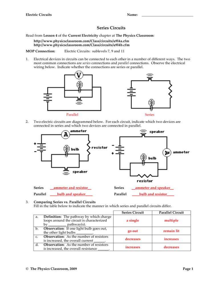
Electric Circuits Name: Series Circuits Read from Lesson 4 of the Current Electricity chapter at The Physics Classroom: http://www.physicsclassroom.com/Class/circuits/u9l4a.cfm http://www.physicsclassroom.com/Class/circuits/u9l4b.cfm MOP Connection: 1. Electric Circuits: sublevels 7, 9 and 11 Electrical devices in circuits can be connected to each other in a number of different ways. The two most common connections are series connections and parallel connections. Observe the electrical wiring below. Indicate whether the connections are series or parallel. Parallel 2. 3. Series Two electric circuits are diagrammed below. For each circuit, indicate which two devices are connected in series and which two devices are connected in parallel. Series __ammeter and resistor__ Series __ammeter and speaker__ Parallel ____bulb and speaker____ Parallel ____bulb and resistor____ Comparing Series vs. Parallel Circuits Fill in the table below to indicate the manner in which series and parallel circuits differ. a. b. c. d. Definition: The pathway by which charge loops around the circuit is characterized by __________ pathway(s). Observation: If one light bulb goes out, the other light bulbs _________. Observation: As the number of resistors is increased, the overall current ______. Observation: As the number of resistors is increased, the overall resistance ______. © The Physics Classroom, 2009 Series Circuit Parallel Circuit a single multiple go out remain lit decreases increases increases decreases Page 1 Electric Circuits 4. The following diagrams represent circuits consisting of two electrical devices connected in series. For each diagram, fill in the blanks to show the voltage drop across the designated device. -40 -5 The electric potential gained by a charge when passing through a battery is equal to the total electric potential lost when traveling around the external circuit. In equation form: ∆Vtot = ∆V1 + ∆V2 + ∆V3 + … . 5. 5. Consider the following two diagrams of series circuits. For each diagram, use arrows to indicate the direction of the conventional current. Then, make comparisons of the voltage and the current at the designated points for each diagram. VA __>__ VG (>,<, or =) VA __<__ VF (>,<, or =) VB __>__ VC (>,<, or =) VB __<__ VC (>,<, or =) VB __>__ VF (>,<, or =) VD __≈__ VF (>,<, or =) IA __=__ IG (>,<, or =) IA __=__ IF (>,<, or =) Express your understanding of equivalent resistance by filling in the blanks. Having two 4-Ω resistors in series is equivalent to having one __8__-Ω resistor. Having three 4-Ω resistors in series is equivalent to having one __12__-Ω resistor. Having four 4-Ω resistors in series is equivalent to having one __16__-Ω resistor. 6. TRUE or FALSE: Three light bulbs are connected in series. The filament of one of the light bulbs burns out. The remaining two light bulbs will still be lit; yet, their brightness will be noticeably less. Answer: FALSE. The other bulbs will go out as well. © The Physics Classroom, 2009 Page 2 Electric Circuits 7. Name: Analyze the following circuit and determine the equivalent or total resistance. Then determine the current at the ammeter location. Rtot = ____6 Ω____ Rtot = ____12 Ω____ I = ____2 A____ I = ____0.5 A____ The total resistance (a.k.a., equivalent resistance) is determined by adding the individual resistance values. The current is then determined using ∆V=I•Rtot where ∆V is the battery voltage. 8. For the following diagrams, utilize the concept of equivalent resistance and Ohm's Law in order to fill in the blank. 6 2 2 Ω 18 Circuit A: Rtot = 30 Ω + 30Ω = 60 Ω; I = ∆V / Rtot = (120 V) / (60 Ω) = 2 A Circuit B: Rtot = ∆V / I = (24 V) / (2 A) = 12 Ω; Circuit C: Rtot = ∆V / I = (24 V) / (2.4 A) = 10 Ω; Circuit D: Rtot = 2 Ω + 2 Ω + 2 Ω = 6 Ω; © The Physics Classroom, 2009 V Rtot= 12 Ω = 4 Ω + R2 + 2 Ω ; R2 = 6 Ω Rtot= 10 Ω = 2 Ω + 4 Ω + 2 Ω+ R4 ; R4 = 2 Ω ∆V = I•Rtot = (3.0 A)•(6 Ω) = 18 V Page 3 Electric Circuits 9. Compare circuits X and Y. Consider circuits X and Y below. Each circuit is powered by the same battery and contains identical resistors. Circuit X has one resistor and circuit Y has two resistors. The equivalent resistance of circuit X will be __<__ (> or < or =) that of circuit Y. The current in the battery in X will be __>__ (> or < or =) that in the battery in Y. 10. Three identical light bulbs are connected to a battery as shown below. Which adjustments could be made to the circuit that would increase the current being measured at X? Circle all that apply. Answer: BEF a. Increase the resistance of one of the bulbs. b. Decrease the resistance of two of the bulbs. c. Increase the resistance of two of the bulbs. d. Decrease the voltage of the battery. e. Increase the voltage of the battery. f. Remove one of the bulbs (and re-connect the circuit). 11. Three identical light bulbs are connected to a battery as shown below. W, X, Y and Z represent locations along the circuit. Which one of the following statements is true? Answer: D a. The potential difference between X and Y is greater than that between Y and Z. b. The potential difference between X and Y is greater than that between Y and W. c. The potential difference between Y and Z is greater than that W between Y and W. d. The potential difference between X and Z is greater than that between Z and W. e. The potential difference between X and W is greater than that across the battery. f. The potential difference between X and Y is greater than that between Z and W. 12. Three identical light bulbs are connected to a battery as shown below. Which one of the following statements is true? Answer: A a. All three bulbs will have the same brightness. b. The bulb between X and Y will be the brightest. c. The bulb between Y and Z will be the brightest. d. The bulb between Z and the battery will be the brightest. Justify your answer to this question using the language of physics. The current in a series circuit is everywhere the same. So the current is the same in each bulb. The bulbs are identical so the resistance is the same. Power - the rate at which energy is transformed by a bulb depends on I and R (P=I2•R) and is the quantity that determines bulb brightness. With the same I and R, the bulbs have identical power and brightness. W 13. Compare a circuit with three light bulbs to a circuit with two light bulbs. All light bulbs are identical. In which circuit will the overall power be the greatest? Intelligently defend your answer. Power can be calculated as the product of I•∆V. Assuming each circuit is powered by the same battery, the ∆V across the whole circuit will be the same for each circuit. Yet the current will be greatest in the 2-bulb circuit since adding more resistors (light bulbs) decreases the current. So the I•∆V product will be greatest for the 2-bulb circuit; it will have the greatest overall power. © The Physics Classroom, 2009 Page 4


