SPEC-10955 Rev A
advertisement
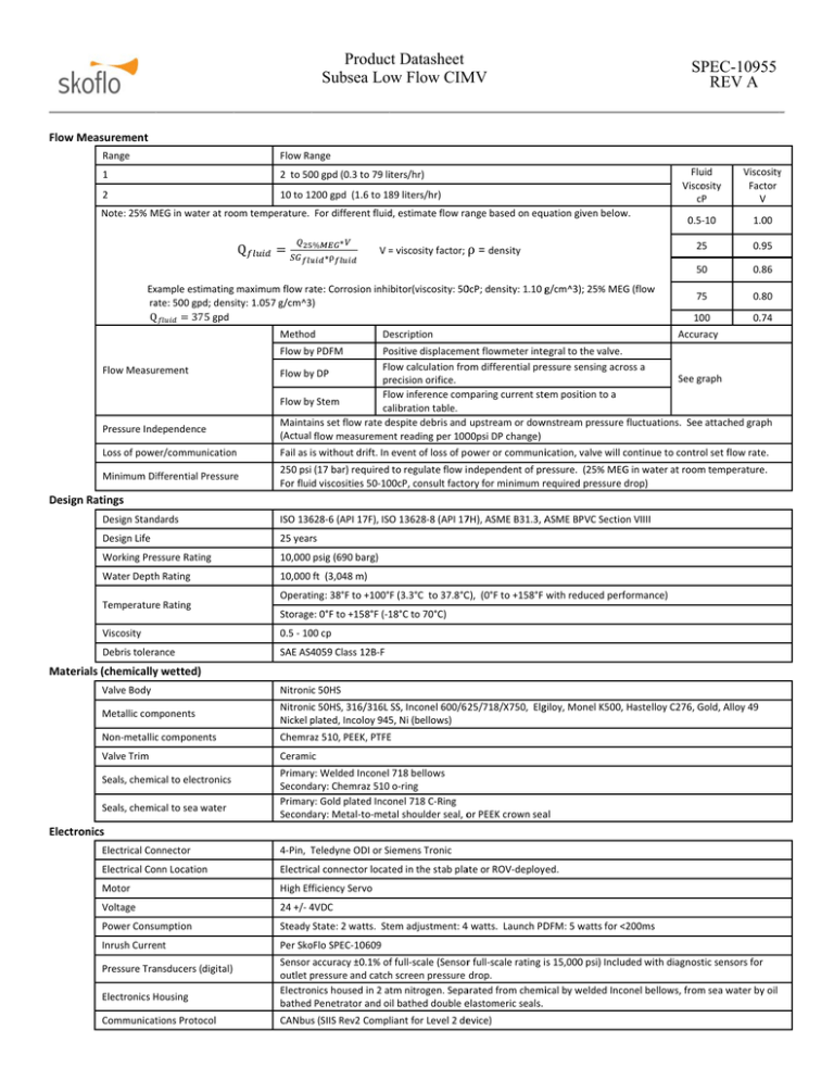
Producct Datasheet Subsea Lo ow Flow CIM MV SP PEC-10955 REV A Flow M Measurement Range Flow Raange 1 2 to 50 00 gpd (0.3 to 79 liiters/hr) 2 10 to 1200 gpd (1.6 to 18 89 liters/hr) Note: 25% M MEG in water at room temperature. For different fluid d, estimate flow raange based on equuation given below w. Q ∗ % ∗⍴ V = = viscosity factor; ⍴ = density Exxample estimating maximum flow raate: Corrosion inhibitor(viscosity: 500cP; density: 1.10 gg/cm^3); 25% MEG G (flow raate: 500 gpd; denssity: 1.057 g/cm^3) Q 375 gpd Method d Description Flu uid Visco osity cP y Viscosity Factor V 0.5‐10 1.00 25 0.95 50 0.86 775 0.80 1000 0.74 Accurracy Flow byy PDFM Flow Measurement Pressure Ind dependence Po ositive displacemeent flowmeter inteegral to the valve. Flow calculation froom differential preessure sensing across a Flow byy DP See ggraph prrecision orifice. mparing current steem position to a Flow inference com Flow byy Stem caalibration table. Maintains set flow rate d despite debris and upstream or dow wnstream pressure fluctuations. Seee attached graph (Actual flow measuremen nt reading per 10000psi DP change) Loss of powe er/communication n Fail as is without drift. In event of loss of poower or communiication, valve will ccontinue to contro ol set flow rate. Minimum Diifferential Pressure G in water at room m temperature. 250 psi (17 bar) required to regulate flow i ndependent of prressure. (25% MEG 00cP, consult factoory for minimum rrequired pressure drop) For fluid viscosities 50‐10 Design n Ratings Design Stand dards ISO 136 628‐6 (API 17F), ISO 13628‐8 (API 177H), ASME B31.3, A ASME BPVC Sectio on VIIII Design Life 25 yearrs Working Pre essure Rating 10,000 psig (690 barg) Water Depth h Rating 10,000 ft (3,048 m) Temperature e Rating Operating: 38°F to +100°F (3.3°C to 37.8°CC), (0°F to +158°F with reduced perfformance) Storage e: 0°F to +158°F (‐1 18°C to 70°C) Viscosity 0.5 ‐ 10 00 cp Debris toleraance SAE AS4 4059 Class 12B‐F Materrials (chemicallyy wetted) Valve Body Nitronicc 50HS Metallic com mponents Nitronicc 50HS, 316/316L SS, Inconel 600/6 25/718/X750, Elggiloy, Monel K500, Hastelloy C276, G Gold, Alloy 49 Nickel p plated, Incoloy 945 5, Ni (bellows) Non‐metallicc components Chemraaz 510, PEEK, PTFEE Valve Trim Ceramic Seals, chemical to electronics Seals, chemical to sea water Primaryy: Welded Inconel 718 bellows Secondary: Chemraz 510 o‐ring Primaryy: Gold plated Inco onel 718 C‐Ring Secondary: Metal‐to‐mettal shoulder seal, oor PEEK crown seaal Electrronics Electrical Connector 4‐Pin, TTeledyne ODI or Siemens Tronic Electrical Conn Location Electriccal connector locatted in the stab plaate or ROV‐deploy ed. Motor High Efficiency Servo Voltage 24 +/‐ 4 4VDC Power Consu umption Steady State: 2 watts. Stem adjustment: 44 watts. Launch PD DFM: 5 watts for <<200ms Inrush Curre ent Per Sko oFlo SPEC‐10609 Pressure Traansducers (digital) Electronics H Housing Communicattions Protocol Sensor accuracy ±0.1% off full‐scale (Sensorr full‐scale rating i s 15,000 psi) Inclu uded with diagnosttic sensors for pressure and catch h screen pressure drop. outlet p Electronics housed in 2 atm nitrogen. Sepaarated from chemiical by welded Inconel bellows, from m sea water by oil bathed Penetrator and oil bathed double eelastomeric seals. CANbuss (SIIS Rev2 Compliant for Level 2 deevice) Producct Datasheet Subsea Lo ow Flow CIM MV SP PEC-10955 REV A % of Reading Flow w measurement accuracyy, % of Read ding, Flow range 2‐500 gpd ±3% ±5% % ±10% Flow rangge 2‐ 500 GPD % of Reading change per 1000psi DP change Pressure independence, % o of Reading ch hange per 10 000 psi DP cchange, Flow w range 2‐50 00 gpd ±5% Flow rangge 2‐ 500 GPD
