EE 321 Analog Electronics, Fall 2011 Homework #1 solution
advertisement
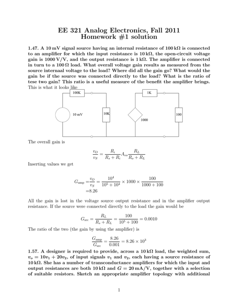
EE 321 Analog Electronics, Fall 2011 Homework #1 solution 1.47. A 10 mV signal source having an internal resistance of 100 kΩ is connected to an amplifier for which the input resistance is 10 kΩ, the open-circuit voltage gain is 1000 V/V, and the output resistance is 1 kΩ. The amplifier is connected in turn to a 100 Ω load. What overall voltage gain results as measured from the source internaal voltage to the load? Where did all the gain go? What would the gain be if the source was connected directly to the load? What is the ratio of tese two gain? This ratio is a useful measure of the benefit the amplifier brings. This is what it looks like 100K 1K 10K 10 mV 100 1000 The overall gain is Ri RL vO = Avo vS Rs + Ri Ro + RL Inserting values we get vO 104 100 = 5 × 1000 × 4 vS 10 + 10 1000 + 100 =8.26 Gamp = All the gain is lost in the voltage source output resistance and in the amplifier output resistance. If the source were connected directly to the load the gain would be Gsrc = RL 100 = 5 = 0.0010 Rs + RL 10 + 100 The ratio of the two (the gain by using the amplifier) is Gamp 8.26 = = 8.26 × 10³ Gsrc 0.001 1.57. A designer is required to provide, across a 10 kΩ load, the weighted sum, vo = 10v1 + 20v2 , of input signals v1 and v2 , each having a source resistance of 10 kΩ. She has a number of transconductance amplifiers for which the input and output resistances are both 10 kΩ and G = 20 mA/V, together with a selection of suitable resistors. Sketch an appropriate amplifier topology with additional 1 resistors selected to provide the desired result. (Hint: In your design, arrange to add currents. In a transconductance amplifier an output current is proportional to the input voltage. We can add voltages by adding currents on the output. That can be done by putting two transconductance amplifiers in paralled across the output. We can then adjust the gain by adjusting the amount of voltage applied across the input, by placing a resistor either in parallel or in series across the input. If there is not enough gain in the amplifier to achieve the output formula we can cascade another set of amplifiers. Assuming that there is enough gain, the circuit could look like this: R2 R1 Rs Rs vi1 Ri gmvi1 Ro RL Ro gmvi2 Ri vi2 v2 v1 We can solve this problem with superposition. The relationship between the output voltage, vO , across RL , and the input voltage v1 , is Ri vO = gm RO ||RO ||RL v1 RS + R1 + Ri We know the values of all the constant except R1 , and we want to choose it such that the ratio vvO1 = 10. Rearranging it we get v1 Ri gm (RO ||RO ||RL) − Rs − Ri vO =0.1 × 10 × 103 × 20 × 10−3 × 104 ||104 ||104 − 20 × 103 =46.7 kΩ R1 = Similarly we can find R2 from v2 Ri gm (RO ||RO ||RL) − Rs − Ri vO =0.05 × 10 × 103 × 20 × 10−3 104 ||104 ||104 − 20 × 103 =13.3 kΩ R2 = If instead we place R1 and R2 in parallel with the input the expression for R1 ||Ri vO = gm (RO ||RO ||RL ) v1 RS + R1 ||Ri vO = R1 ||Ri gm (RO ||RO ||RL ) (RS + R1 ||Ri ) v1 2 vO v1 becomes R1 ||Ri vO vO − gm (RO ||RO ||RL) = −RS v1 v1 R1 ||Ri = = Rs vvO1 gm (RO ||RO ||RL) − vO v1 10 × 103 × 10 1 20 × 10−3 × 3×10 −4 − 10 =1.76 kΩ In which case R1 = = 1 1 R1 ||Ri − 1 1 1.76×10³ 1 Ri − 1 104 =2.14 kΩ Similarly, R2 ||Ri = = Rs vvO2 gm (RO ||RO ||RL ) − vO v2 10 × 103 × 20 1 20 × 10−3 × 3×10 −4 − 20 =4.29 kΩ and R2 = = 1 1 R2 ||Ri − 1 1 4.29×10³ 1 Ri − 1 104 =7.51 kΩ 1.58. Figure P1.58 shows a transconductance amplifier whose output is fed back to its input. Find the input resistance Rin of the resulting one-port network. (Hint: Apply a test voltage vx between the two input terminals, and find the current ix drawn from the source. Then Rin = vx/ix. 3 If we apply vx on the input, then we apply vi across Ri . The current through Ri is then iin = vx Ri The current through the current source (from top to bottom) is iout = gm vx The sum of those currents must be supplied by the source, so 1 vx + gm vx = vx gm + ix = Ri Ri The input resistance is then Rin = vx 1 = ix gm + 1 Ri = Ri 1 + gm Ri The input resistance is thus smaller with the feedback than without the feedback. 4


