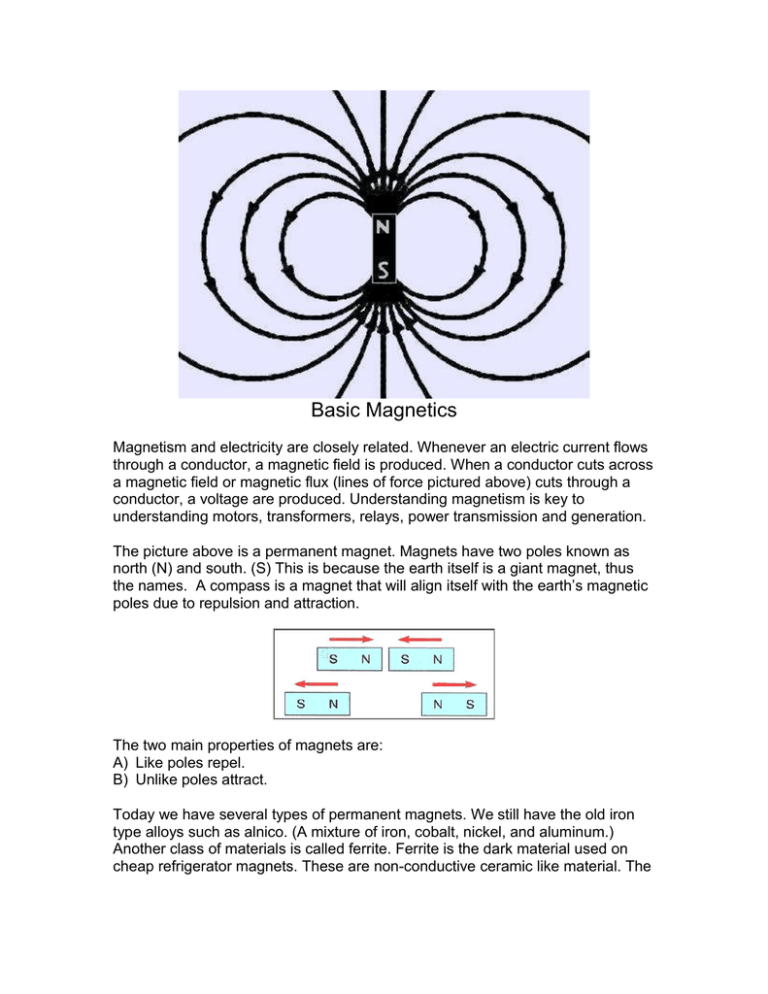
Basic Magnetics
advertisement

Basic Magnetics Magnetism and electricity are closely related. Whenever an electric current flows through a conductor, a magnetic field is produced. When a conductor cuts across a magnetic field or magnetic flux (lines of force pictured above) cuts through a conductor, a voltage are produced. Understanding magnetism is key to understanding motors, transformers, relays, power transmission and generation. The picture above is a permanent magnet. Magnets have two poles known as north (N) and south. (S) This is because the earth itself is a giant magnet, thus the names. A compass is a magnet that will align itself with the earth’s magnetic poles due to repulsion and attraction. The two main properties of magnets are: A) Like poles repel. B) Unlike poles attract. Today we have several types of permanent magnets. We still have the old iron type alloys such as alnico. (A mixture of iron, cobalt, nickel, and aluminum.) Another class of materials is called ferrite. Ferrite is the dark material used on cheap refrigerator magnets. These are non-conductive ceramic like material. The final class are rare-earth super magnets, the most powerful of all. What follow is from our textbook (page 80), which I differ on. MAGNETIC MATERIALS Magnetic materials can be divided into three basic classifications. These are: Ferromagnetic Materials: These materials are metals that are easily magnetized. Examples of these materials are iron, nickel, cobalt, and manganese. Paramagnetic Materials: These materials can be magnetized, but not as easily as ferromagnetic materials. Some examples of paramagnetic materials are platinum, titanium, and chromium. Diamagnetic Materials: These are materials that cannot be magnetized. The magnetic lines of force tend to go around them instead of through them. Some examples of these materials are copper, brass, and antimony. (They forgot aluminum, graphite, and bismuth.) Shown above is a "neodymium" or "rare earth" super magnet like the ones I’ve removed from junk computer hard drives. Some of the best materials for the production of permanent magnets are alloys such as Alnico 5, which is made from a combination of aluminum, nickel, cobalt, copper, and iron. Another type of permanent magnet material is made from a combination of barium ferrite and strontium ferrite. Ferrites can have an advantage in some situations because they are insulators and not conductors. Neodymium-iron-boron “super magnets” while often nickel coated, are really more like a ceramic. All of the above are permanent magnets. Electromagnets The magnetic field produced in a conductor is relatively weak and is proportional to the current moving through the conductor. The higher the current flow, the stronger the magnetic field produced. This is what we measure with a clamp on ampmeter. The strength of the magnetic field isn’t infinite and we reach point of saturation where an increase in current produces no further magnetic flux. Winding a conductor such as wire into a coil will greatly increase the magnetic field. In fact the more turns of wire produces a stronger magnetic field with no increase in current. Note: the magnetic polarity is dependent on the direction of current flow. What we have is called an electromagnet. An electromagnet is temporary. As long as current flows we have a magnetic field. By inserting an iron rod or other magnetic material into the coil, we again greatly increase the magnetic force. D'Arsonval galvanometer movement A galvanometer is a type of ammeter, an instrument for detecting and measuring electric current. It is an analog electromechanical device (transducer) that produces a rotary deflection, through a limited arc, in response to electric current flowing through its coil interacting with a fixed magnet. The first galvanometer used a compass inside a coil of wire was invented in by Hans Oersted in 1820. When a current flows through the coil it creates an electromagnet that is repelled to or attracted to the fixed magnet. If the polarity of the current is reversed the meter needle will move in the opposite direction. Too much current in either direction will damage the mechanical movement or the coil. Expanding the meter with Ohms Law In many cases resistors are placed in series with the coil to read higher voltages. For example let’s assume the coil in the above meter has a resistance (the copper wire) of 1000 ohms and a full-scale deflection current (all the way to the right) of 1 mA. Using ohms law 1000 ohms times .001 amp = 1 volt. (Make sure to change mA to amps by dividing by 1000!) So one volt will give us full-scale deflection, how do we measure 10 volts? To extend the range of our basic 1-volt voltmeter we place a multiplier resistor in series. We calculate a value that will drop 9-volts of the 10-volts. Again we use ohms law knowing that a series circuit the current through the meter and the multiplier resistor will be 1 mA. Thus 9-volts divided by .001 amp = 9000 ohms. (9k) Above is an exposure meter from a camera. Replace the multiplier resistor with a photocell and potentiometer (for calibration) in series with the meter and internal battery. Shown above is our basic 1-volt voltmeter configured as an ammeter. Let’s assume we want to measure 100 mA. That would destroy our 1 mA meter so we use a shunt resistor to carry the excess current around the meter movement. Again ohms law comes to the rescue. Because the resistor is parallel to the meter, they have the same voltage that at max current is one volt. We know 99 mA must flow through the resistor. So our voltage will 1 volt divided by .099 amp will give us a total resistance of about 10.1 ohms. So far we have discussed only DC voltmeters and ammeters. We will discuss AC voltmeters and ammeters in AC. This document is for educational purposes only and comes with no warranty. Published under the terms and conditions of the Creative Commons License. See http://creativecommons.org/licenses/by/1.0/ For more on electronics see http://www.bristolwatch.com


