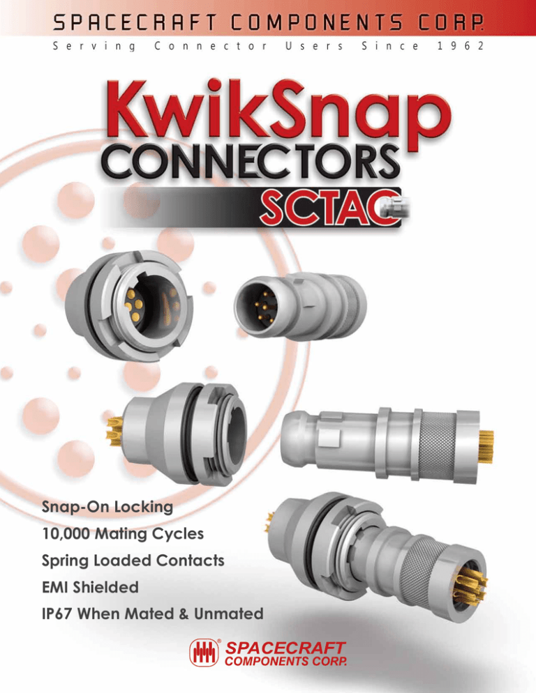
Snap-On Locking 10,000 Mating Cycles Spring Loaded Contacts
advertisement

Snap-On Locking 10,000 Mating Cycles Spring Loaded Contacts EMI Shielded IP67 When Mated & Unmated Ordering Information SCTAC 1 07 S N Z 1 SERIES PREFIX Style 1 2 3 4 5 6 7 Pin Placement BLANK Standard Contacts 1 Center Pin Advanced by 1mm Straight Plug▲ Receptacle - Rear Panel Mounting Receptacle - In-Line▲ Receptacle - Front Panel Mounting Receptacle - Rear Panel Mounting▲ Plug - Front Panel Mounting Plug - Rear Panel Mounting▲ ▲ PLATING B Black Oxide Coating, Material: Stainless Steel 303 C Black Oxide Coating, Material: Stainless Steel 316 N Nickel Plated, Material: Aluminum Alloy P Passivated, Material: Stainless Steel 303 R Passivated, Material: Stainless Steel 316 W Tungsten Carbide Black, Material: Stainless Steel 303 X Tungsten Carbide Black, Material: Stainless Steel 316 Z Zinc Cobalt Plated, Material: Aluminum Alloy Banding or Overmolding application. NO. OF CONTACTS 07 7 Contacts 13 13 Contacts 19 19 Contacts POLARIZATION See Illustration below Pin Mating Side Termination S Solder Cup (24-28 AWG) B P.C. Tail Termination, Diameter = .024 (0.06) P.C. Tail Length = .118 (3.00) N A B C D E F Receptacle Mating Side N A B C D E Pin Side CENTER PIN ADVANCED BY 1MM .036 (0.90) F Recept. Side .097 (2.46) .091 (2.31) .110 (2.79) .101 (2.56) .056 (1.40) .050 (1.27) .070 (1.78) .060 (1.52) .137 (3.50) SCTAC2* Receptacle, Rear Panel Mount SCTAC1* Straight Plug PLUG WITH PIN CONTACTS RECEPTACLE WITH SOCKET CONTACTS NO.OF CONTACTS ØX ØY Z 7 .433 (11.00) .606 (15.40) M12 x 0.75 13 .543 (13.80) .724 (18.40) M15 x 0.75 19 .582 (14.80) .591 (19.40) M16 x 0.75 NO.OF CONTACTS ØA ØB 7 .327 (8.30) .402 (10.20) Panel Cut-Out Dimensions 13 .445(11.30) .512 (13.00) 19 .484 (12.30) .551 (14.00) Insert Configurations Plug Mating Side Pin 1 Pin 1 Pin 1 Pin 7* Pin 19* Pin 13* 7 13 19 * Last pin advanced by 1mm. NO. OF CONTACTS ØS +.004 (.10) -.000 (.00) T +.004 (.10) -.000 (.00) 7 .480 (12.20) .465 (11.80) 13 .598 (15.20) .579 (14.70) 19 .638 (16.20) .618 (15.70) Receptacle Mating Side Pin 1 Pin 1 Pin 1 Pin 7 Pin 19 Pin 13 7 13 19 Number of .031Ø Spring Loaded Pin Contacts 3040 Clayton Street North Las Vegas, NV 89032 Phone: 702-851-7600 Fax: 702-851-7620 Email: salesinfo@spacecraft.com Web: www.spacecraft.com Dimensions In-Line RECEPTACLE SCTAC3* NO.OF CONTACTS ØX Receptacle - Front Panel MOUNTING SCTAC4* NO.OF CONTACTS ØY ØX ØY Receptacle - Rear Panel MOUNTING SCTAC5* Z THREADS NO.OF CONTACTS ØX ØY Z THREADS 7 .402 (10.20) .512 (13.00) 7 .472 (12.00) .606 (15.40) M12 x 0.75 7 .402 (10.20) .606 (15.40) M12 x 0.75 13 .512 (13.00) .630 (16.00) 13 .591 (15.00) .724 (18.40) M15 x 0.75 13 .512 (13.00) .724 (18.40) M15 x 0.75 19 .551 (14.00) .669 (17.00) 19 .630 (16.00) .591 (19.40) M16 x 0.75 19 .551 (14.00) .591 (19.40) M16 x 0.75 Plug - Front Panel MOUNTING SCTAC6* NO.OF CONTACTS ØX ØY Plug - REAR Panel MOUNTING SCTAC7* Z THREADS NO.OF CONTACTS ØX ØY Z THREADS 7 .327 (8.30) .606 (15.40) M12 x 0.75 7 .327 (8.30) 13 .445 (11.30) .724 (18.40) M15 x 0.75 13 .445 (11.30) .724 (18.40) M15 x 0.75 .606 (15.40) M12 x 0.75 19 .484 (12.30) .591 (19.40) M16 x 0.75 19 .484 (12.30) .591 (19.40) M16 x 0.75 Over-amolded cable assemblies are available. Applicable Documents Base Material - Standard Specifications MIL-M-24519 ASTM-B-16 ASTM-B-121 ASTM-B-139 ASTM-B-196 ASTM-B-197 ASTM-B-209 ASTM-B-455 ASTM-A-582 Moulding Plastics, Electrical, Thermoplastic Free-Cutting Brass Rod, Bar and Shapes Leaded Brass Plate, Sheet, Strip, and Rolled Bar Standard Specification for Phosphor Bronze Rod, Bar, and Shapes Copper-Beryllium Alloy Rod and Bar Copper Beryllium Alloy Wire Aluminum and Aluminum-Alloy Sheet and Plate Standard Specification for Copper-Zinc-Lead Alloy (Leaded-Brass) Extruded Shapes Free-Machining Stainless Steel Bars and Heat Resisting Steel Bars Plating - Standard Specifications AMS-C-26074 MIL-STD-869 ASTM-B-488 ASTM-A-967 QQ-N-290 Test Procedures Coatings, Electroless Nickel Standard Specification for Flame Spraying Electrodeposited Coatings of Gold Chemical Passivation Treatments for Stainless Steel Parts Nickel Plating, Electrodeposited 3040 Clayton Street North Las Vegas, NV 89032 EIA 364 UL94 IEC 529 IEC 512 Test Methods For Electrical Connectors Test Methods For Flammability Rating Degrees of protection provided by enclosures Electromechanical components for electronic equipment Phone: 702-851-7600 Fax: 702-851-7620 Email: salesinfo@spacecraft.com Web: www.spacecraft.com Circular Connector Technical Characteristics General Materials and Plating Number of Contacts Receptacle Contact Termination Plug Contact Termination AWG Contact Cable Diameter Range 7, 13, 19 Solder Cup, Straight PCB Solder Cup 28-24 Max 6 mm (7 contacts) Max 7.5 mm (13 contacts) Max 8.5 mm (19 contacts) Inner Insulators Interface Insulators Housing Locking Spring GE Ultem 2300 Black GE Ultem 2300 Black (see table 1 below) 316BRT Stainless Steel Materials and Plating Plug Contact Terminations (solder cups) Spring Contact Clip Spring Element Receptacle Contact Weight CnZn36Pb3 plated 5µm Sn/2.5µm Ni or plated Au per ASTM-B-488 CuBe as per ASTM-B-197 plated with Au as per ASTM-B-488 Stainless Steel AISI 302 passivated as per ASTM-A-967 CnZn36Pb3 plated with Au as per ASTM-B-488 Related to standard connectors configuration (see table 2 below) Table 1 - Plating Aluminium Alloy MATERIAL CODE PLATING 6061T6 Z Zn/Co on Chemical Ni Black 5 µm SAE AMS-C-26074 Class 1 Table 2 - Connector Weight Stainless Steel AISI303 - ASTM-B-582 N Chemical Ni Matt Grey 20 µm SAE AMS-C-26074 Class 1 Grade A Size AISI316 - ASTM-B-582 P, R B, C Passivation Coating Oxide Matt Grey Black as per as per MIL-DTL-13924D ASTM-A-967 07 W, X Metal Spraying Tungsten Carbide Black 1-5 µm as per MIL-STD-869 13 19 Material Aluminum Stainless Steel Aluminum Stainless Steel Aluminum Stainless Steel PLUG 4.0 7.6 6.7 11.4 8.4 13.7 RECEP. 4.8 10.2 6.5 13.5 7.1 15.1 Weight measured in grams. Electrical Characteristics EMI Shielding Current Rating Dielectric Withstanding Voltage (between contacts) Contact Resistance (low level) Insulation Resistance Electrical Bonding Resistance 360° shield coverage 3A@25°C for each contact according to IEC 512-3 500 Vrms at sea level and 150 Vrms at 21336m according to EIA 364.20 <25 mΩ for each contact according to EIA 364.6 5000 MΩ @ 500V d.c. according to EIA364.21 (see table 3) Table 3 - E lectrical Bonding Resistance vs. Material/Surface Treatment Z 500 800 mΩ N 58 mΩ P, R 58 mΩ B, C 150 250 mΩ W, X 20 40 mΩ Mechanical and Environmental Characteristics Temperature Range Temperature cycling Salt Spray -55°C +85°C EIA364.32 Method A EIA364.26 Condition A mated connectors Humidity EIA364.31 Method IV IP Level 67 mated and unmated IEC 529 Vibration EIA364.28 Condition III Shock EIA364.27 Condition G Contact Spring Force (single contact) Max 1.5 [N] Connector Mating / Unmating Force EIA364.09 (see table 4) Headquarters 3040 Clayton Street North Las Vegas, NV 89032 Florida Office 4577 Nob Hill Road Suite 106 Sunrise, FL 33351 Tel: 954.748.4540 Fax: 954.748.4128 Arizona Office 519 W. Lone Cactus Dr. Suite 401 Phoenix, AZ 85027 Tel: 623.580.1162 Fax: 623.580.1165 Table 4 - Mating / Unmating Forces Size 07 13 19 Material Aluminum Stainless Steel Aluminum Stainless Steel Aluminum Stainless Steel Phone: 702-851-7600 Fax: 702-851-7620 UNMATING [N] Min Max 20 35 20 40 20 35 20 40 25 35 25 45 Phone: 702.851.7600 Fax: 702.851.7620 Italy Office Spacecraft Components, Sp A Milan, Italy +39 (335) 719.4512 3040 Clayton Street North Las Vegas, NV 89032 MATING [N] Min Max LIFE CycleS 2,000 8,000 2,000 10,000 2,000 10,000 Email: salesinfo@spacecraft.com Web: www.spacecraft.com Mexico Office Av. Constituyentes 13-6 Col. Pueblo Nuevo Queretaro, Qro 76900 +52 442 341 69 63 OCT.2012 SF-171 COMPILED AND PRODUCED BY SPACECRAFT COMPONENTS CORP. Email:SPACECRAFT salesinfo@spacecraft.com ©2012 COMPONENTS CORP., NORTH LAS VEGAS, NV 89032 Web: www.spacecraft.com

