RF Modulator
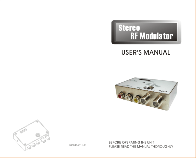
Stereo
RF Modulator
USER'S MANUAL
6060404011-11
USER'S MANUAL
BEFORE OPERATING THE UNIT,
PLEASE READ THIS MANUAL THOROUGHLY
SAFETY INFORMATION
CAUTION
RISK OF ELECTRONIC
SHOCK DO NOT OPEN
CAUTION:
DO NOT REMOVE THE COVER FOR REDUCING THE
RISK OF ELECTRONIC SHOCK
NO USER-SERVICEABLE PARTS INSIDE REFER
SERVICING TO QUALIFIED SERVICE PERSONNEL.
WARNING:
To prevent fire or shock hazard, do not expose the unit to rain or moisture.
Safety term and Symbols
Warning: Warning statements identify conditions or practices that could result in injury or loss of life.
Caution: Caution statements identify conditions or practices that could result in damage to this product or other property.
Danger: Do not remove the cover for reducing the risk of electric shock.
IMPORTANT SAFETY INSTRUCTIONS
1.
All the safety and operating instructions should be read before the product is operated.
2.
The safety and operating instructions should be retained for future reference.
3.
All warnings on the product and in the operating instructions should be adhered to.
4.
All operating and use instructions should be followed.
5.
Unplug this products from the wall outlet before cleaning. Do not use liquid cleaners or aerosol cleaners. Use a damp cloth for the cleaning.
6.
Do not use attachments not recommended by the products manufacturer if they may cause hazards.
7.
Do not use this product near water - for example, near a bath tub, wash bowl, kitchen sink, or laundry tub, in a wet basement, or near a swimming pool; and the like.
8.
Any mounting of the product should follow the manufacturer's instructions, and should use a mounting accessory recommended by the manufacturer.
9.
This product should be operated only from the type of power source indicated on the marking label. If you are not sure of the type or power supply to your home, consult your product dealer or local Power Company. For products intended to operate from battery power, or other sources, refer to the operating instruction.
10.
Power supply cord should be routed so that are not likely to be walked on or pinched by items placed upon or against them, paying particular attention to cords at plugs, or other sources, refer to the operating instructions.
11.
For added protection for this product during a lightning storm, or it is left unattended and unused for long periods of time, unplug it from the wall outlet and disconnect cable system.
This will prevent damage to the product due to lightning and powerline surges.
12.
Never push objects of any kind into this product through openings as they may touch dangerous voltage points or short-out parts that could result in a fire or electronic shock. Never spill liquid of any kind on the product.
13.
Do not overload wall outlets, extension cords, or integral convenience receptacles as this can result in a risk of fire or electric shock.
14.
Unplug this product from the wall outlet and refer servicing to qualified service personnel under the following conditions.
When the power-supply cord or plug is damaged.
If liquid have been spilled, or objects have fallen into the products.
If the product does not operate normally by following the operating instructions, adjust only those controls that are covered by the operating instructions as an improper adjustment of other controls may result in damage and will often require extensive work by a qualified technician to restore this product to its normal operation.
If the products has been dropped or damaged in any way.
When the product exhibits a distinct change in performance - this indicates a need for service.
15.
When replacement parts are required, be sure the service technician has used replacement parts specified by the manufacturer or that have the same characteristics as the original part. Unauthorized substitutions may result in fire, electric shock, or other hazards.
16.
Upon completion of any service or repair to this product, ask the service technician to perform safety checks to determine that the product is in proper operating conditions.
17.
The product should be situated away from heat sources such as radiators, heat registers, stoves, or other products including amplifiers that produce heat.
Table of Contents
3
4
1
2
5
Introduction
1.1 Overview
.............................
...............................
1.2 Main Features
1.3 Applications
1.4 Specification
........................
........................
Check package before use .......
Controls ..................................
Figure Illustration
........................
Installation and Operation .........
5.1 Work with VCD/DVD players .........
5.2 Work with Satellite Receiver .........
5.3 Connect the second load when
AV source just has one output
5.4 Dual power sources
.....
..................
5.5 Channel selection ..................
8
9
10
12
12
5.6 How to check channel selected ...
12
4
7
8
1
2
1
1
1
4
6
7
Trouble Shooting .....................
12
6.1
6.2
No picture or sound ...................
The brightness of image abnormal ................................
12
13
6.3
Interference the adjacent channels ................................
LNB can not work properly ...........
13
6.4
13
6.5
Distortion of sound ..................
13
6.6 Badly work on Remote Control...... 13
Channel Lists ............................. 13
7.1 Table of European Channels ........
14
17
1
Introduction
1.1
Overview
This stereo RF modulator is a programmable modulator which generates an RF
TV channel from a baseband video and audio signal. It is the practical solution of building your home AV network. It can use current cable network in the house to transmit a good quality Audio Video to another room, even remote control the
A/V source on you own way.
1.2
Main Features
PAL B/G stereo
Dip switch channel selector
High output power up to 82dB µ V
Dual input power source
Remote control extension via cable
A/V output for widely application
Cost effective for your own local
CATV system
1.3
Applications
Home AV network
Hotel local TV program system
1
1.4 Specification
RF Modulator
Item
Standard
Frequency Range
Output Power
Harmonic
Third distortion
Isolation
Insertion loss
PAL B/G
Specification
UHF: 470~862MHz
VHF: 126~300MHz
Europe:
Ch. 21 ~69
Ch. S4~S20, E5~E12
Australia:
Ch. 21 ~69
Ch. 6~12
82/72dB µ V (Typical)
>55dBc
>58dBc
>20dBc
<1.5dB@800MHz
<4.0dB@2.3GHz
Audio carrier frequency
Audio frequency response
5.5, 5.742MHz
50-15KHz
Audio input level
Separation
1.7 Vpp max.
>20dB (Typical)
(test frequency:1KHz/1.7Vpp)
Current consumption
Input power
110mA
DC 9V/300mA for adaptor.
13/18V for satellite receiver
Power adaptor DC 9V / 300mA
Operating Temperature 0 C ~ 50 C
Dimension(mm)
IR emitting freq.
IF frequency
IR emitting range
Sensitivity
85.8(L)X68.4(W)X21.3(H)
38kHz.
455kHz
5m Typ.
<-80dBm
2
IR Extender Transmitter
Item
Modulation
Deviation
Center frequency
FSK
5kHz
Specification
27.045MHz / 27.145MHz
27.095MHz / 27.195MHz
5Kbps Max.
Data rate
Output power
Insertion Loss
L.O. leakage to TV port
Current Consumption
-20dBm typ.
<3dB@860MHz
<-80dBm
10mA typ.
Specification subject to change without prior notice.
2
Check package before use
1. RF Modulator
2. IR Transmitter
3. Power Adaptor
(9V 300mA)
4. IR cable
5. SCART to RCA Adaptor
6. Users manual
X 1
X 1
X 2
X 1
X 1
X 1
3
3
Controls
3.1
RF Modulator
Rear View
1 2 3 4 5
1. RF +1 ch output and IR signal input
2. RF input
3. Video Input
4. Audio Left
5. Audio Right
4
Bottom View
6 10 7 8 9
6. Left: DC source switch (DC jack power supply
only if you remove the jumper)
7. Right: Video loaded jumper (unplug when
using video splitter)
Caution:
Do not plug the jumpers horizontally to avoiding any damage in Set-top Box.
8. Channel switch: sw1 to sw7 for channel
switch, sw8 for test pattern on/off (if
sw8 is on, there will be two white bar
on TV screen on the channel that you
selected. sw9 for high /low power.
9. DC jack
10. IR emitter Jack
5
3.2
IR Transmitter
1.
F-Connector (To TV)
2.
3.
F-Connector (RF In)
DC Jack
4. IR Extender Mouse
5.
Power On/Off Button
1
2
3
4
IR Transmitter
5
OFF
ON
IR Extender Mouse
Note 1:
IR mouse built-in a LED, when you use Remote control, LED will flash to indicate signal received.
Note 2:
Because of FSK Modulation designed in IR Transmitter, all IR
Transmitters can not work at the same time. Make sure to power off other IR Extender mouse and only leave one which you are using in the viewing room.
6
4
Figure Illustration
1.
2.
AV Sources:
RF Sources:
VCD/DVD Plays, Satellite Receiver etc..
Satellite/Terrestrial/Cable
Broadcasting or other RF Sources.
Room 1 RF Modulator
CATV or Terrestrial
RF Input
Room 2
Remote
Control
AV Sources
TV
IR Extender mouse
Splitter
Remote
Control
Room 3
IR Extender Tx
TV
IR Extender Tx
TV
7
5
Installation and Operation
5.1
Work with VCD/DVD players.
RF Modulator
TV
VCD Best
VCD/DVD
Figure 1.
CATV or Terrestrial
1.
2.
Turn off all A/V equipments power.
Connect RF modulator and VCD/DVD players by A/V cable.
3.
To connect RF modulator, Television and
RF sources by coaxial cable.
4.
Connect power adaptor with RF modulator and plug it into power socket.
5. Connect the IR Transmitter to TV by coaxial cables.
6. Connect a 9V/300mA power adaptor with
IR Transmitter, then plug the power adaptor into socket outlet,
7.
8.
9.
10.
Turn on the A/V source and television.
Set up the RF Modulator on the empty channel.
Please refer to "5.5 Channel selection"
Check the program signal can be properly transmitted from RF Modulator, and received by the TV ends in other rooms.
Using Remote control to check IR function work smoothly. When you are using Remote Control, the IR Extender mouse built-in a LED will flash to indicate the IR Transmitter has received IR signal.
8
5.2
Work with Satellite Receiver.
Diplexer Combiner
LNB
AV
RF Modulator
Figure 2.
DIO
Receiver
Enjoy your life
Receiver
1.
2.
3.
4.
Turn off all A/V equipments power.
Connect RF modulator and satellite receiver by A/V cable.
To connect RF modulator, Television or
Diplexer by coaxial cable.
Satellite receiver can supply power, no extra power needed by RF Modulator.
5.
6.
7.
8.
Connect the IR Transmitter to TV by coaxial cables.
Connect a 9V/300mA power adaptor with
IR Transmitter, then plug the power adaptor into socket outlet,
Turn on the A/V source and television.
Set up the RF Modulator on the empty channel.
Please refer to "5.5 Channel selection"
9
9.
10.
Check the program signal can be properly transmitted from RF Modulator, and received by the TV ends in other rooms.
Using Remote control to check IR function work smoothly. When you are using Remote Control, the IR Extender mouse built-in a LED will flash to indicate the Diplexer has received IR signal.
5.3 Connect the second load when
AV source has just one output
This RF Modulator offers an extended loop through function. Satellite receiver can transmit program to the TV beside it through
AV cable with high quality AV signal, and it can also transmit the program to the other rooms through the RF modulator.
Diplexer
Combiner
LNB
AV
Receiver
SCART to RCA
AV
AV
RF Modulator
Figure 3.
10
1.
2.
Turn off all A/V equipments power.
Connect RF modulator , television and satellite receiver by SCART to RCA Adaptor.(refer to
Figure 3.)
3.
4.
To connect RF modulator, satellite receiver or
Diplexer by coaxial cable.
5.
Satellite receiver can supply power, no extra power needed by RF Modulator.
Please refer to "5.4 Dual power sources".
6.
Connect a 9V/300mA power adaptor with
IR Transmitter, then plug the power adaptor into socket outlet,
7.
8.
Turn on the A/V source and television.
Set up the RF Modulator on the empty channel.
9.
Please refer to "5.5 Channel selection"
Check the program signal can be properly transmitted from RF Modulator, and received by the TV ends in other rooms.
10.
Using Remote control to check IR function work smoothly. When you are using Remote Control, the IR Extender mouse built-in a LED will flash to indicate the Diplexer has received IR signal.
11
5.4
Dual power sources
The RF Modulator can use the power from adaptor or satellite receiver. If you connect to both power source at same time, the higher one will be used ( normally, the DC power from satellite receiver will be 13/18V,
5.5
5.6
can force the modulator using the power from Power Adaptor.
Channel selection
This RF modulator is designed in double side band modulation that occupies two channel space. The program you are going to have in your home network should be placed at the higher channel of at least two continuous empty channels, and it is better to set program on the middle of three continuous empty channel.
How to check channel selected
This RF Modulator offers an internal video test pattern- if you switch sw8 to 1, and TV screen shows up black and white bars, that is you have gotten the correct channel.
E5:11010010
ON
Switch sw8 to 1
ON
1 2 3
1 1 0
4
1
5
0
6 7 8
0 1 0
9 1 2 3
1 1 0
4
1
5
0
6 7 8
0 1 1
9
Internal video test pattern
Trouble Shooting
6
6.1 No picture or sound
Check all the cables well and connected rightly.
Check the channels correctly set up. Please refer to "5.6 How to check channel selected".
12
6.2
The brightness of image abnormal
6.3
6.4
is other loading or it is connecting with TV.
Interfere the adjacent channels:
Re-set up the program to other empty channel.
Please refer to "5.5 Channel Selection".
LNB can not work properly
6.5
adaptor to force RF modulator consuming power from socket outlet instead of that from satellite receiver.
Distortion of sound
Turn down the volume of AV source.
6.6
Badly work on Remote Control
Check all the cables well and connected rightly.
Check the adaptor rightly connected and well.
Make sure the Power Button on IR Extender Mouse of Transmitter at " Power On" mode.
Make sure other IR Extender mouses have been powered off.
7
Check if the remote controller is out of battery.
Make sure your remote controller is able to align the IR Extender.
Make sure the range between remote controller and IR Extender Mouse is less than 10m.
Check if the IR Extender Mouse of Receiver is rightly positioned in front of the AV Sources.
Channel Lists
Adjust Dip switch to get the channel.
E5:11010010 E6:00110010
ON ON
1 2 3
1 1 0
4
1
5
0
6 7 8
0 1 0
9 1 2 3
0 0 1
4
1
5
0
6 7 8
0 1 0
9
13
7.1 Table of European Channels
Channel Video carrier
Switch position
12345678
E6
E7
E8
E9
E10
E11
A
E2
E3
E4
E5
E12
S1
S2
S3
S4
S5
S6
S7
S8
S9
S10
S11
S12
S13
S14
S15
168.25
231.25
238.25
245.25
252.25
259.25
Frequency range:126-300MHz
224.25
183.75
192.25
201.25
126.25
133.25
140.25
147.25
154.25
161.25
53.75
48.25
55.25
62.25
175.25
182.25
189.25
196.25
203.25
210.25
217.25
11100010
00010010
10010010
01010010
11010010
00110010
10110010
01110010
11110010
00001010
10001010
01001010
10000000
01000000
11000000
00100000
10100000
01100000
11100000
00010000
10010000
01010000
11010000
00110000
10110000
01110000
11110000
14
Channel Video carrier
Switch position
12345678
21
22
23
24
25
26
S16
S17
S18
S19
S20
27
28
29
30
31
32
33
34
35
36
37
38
39
40
41
42
599.25
607.25
615.25
623.25
631.25
639.25
Frequency range:126-300MHz
519.25
527.25
535.25
543.25
551.25
559.25
567.25
575.25
583.25
591.25
266.25
273.25
280.25
287.25
294.25
471.25
479.25
487.25
495.25
503.25
511.25
00001000
10001000
01001000
11001000
00101000
10101000
01101000
11101000
00011000
10011000
01011000
11011000
00111000
10111000
01111000
11111000
00000100
10000100
01000100
11000100
00100100
10100100
01100100
11100100
00010100
10010100
01010100
15
Channel Video carrier
Switch position
12345678
48
49
50
51
52
53
43
44
45
46
47
647.25
655.25
663.25
671.25
679.25
687.25
695.25
703.25
711.25
719.25
727.25
54
55
56
57
58
735.25
743.25
751.25
759.25
767.25
59
60
61
62
63
64
775.25
783.25
791.25
799.25
807.25
65
66
67
815.25
823.25
831.25
68
69
839.25
847.25
855.25
Frequency range: 470-860MHz
11010100
00110100
10110100
01110100
11110100
00001100
10001100
01001100
11001100
00101100
10101100
01101100
11101100
00011100
10011100
01011100
11011100
00111100
10111100
01111100
11111100
00000010
10000010
01000010
11000010
00100010
10100010
16
7.2 Table of Australian Channels
Channel
33
34
35
36
37
38
39
26
27
28
29
30
31
32
9A
10
11
12
21
22
23
24
25
8
9
6
7
Video carrier
175.25
182.25
189.25
196.25
203.25
209.25
216.25
224.25
478.25
485.25
492.25
499.25
506.25
513.25
520.25
527.25
534.25
541.25
548.25
555.25
562.25
569.25
576.25
583.25
590.25
597.25
604.25
Switch position
12345678
01100000
11100000
00010000
10010000
01010000
11010000
00110000
10110000
10101000
01101000
11101000
00011000
10011000
01011000
11011000
00111000
10111000
01111000
11111000
00000100
10000100
01000100
11000100
00100100
10100100
01100100
11100100
17
Channel Video
48
49
50
51
52
53
54
55
56
57
58
63
64
65
66
59
60
61
62
40
41
42
43
44
45
46
47
Frequency range: 470-860MHz carrier
611.25
618.25
625.25
632.25
639.25
646.25
653.25
660.25
667.25
674.25
681.25
688.25
695.25
702.25
709.25
716.25
723.25
730.25
737.25
744.25
751.25
758.25
765.25
772.25
779.25
786.25
793.25
Switch position
12345678
00010100
10010100
01010100
11010100
00110100
10110100
01110100
11110100
00001100
10001100
01001100
11001100
00101100
10101100
01101100
11101100
00011100
10011100
01011100
11011100
00111100
10111100
01111100
11111100
00000010
10000010
01000010
18
Channel Video carrier
800.25
807.25
814.25
Switch position
67
68
69
Frequency range: 470-860MHz
12345678
11000010
00100010
10100010
19 20
