Chapter 31 Solutions
advertisement
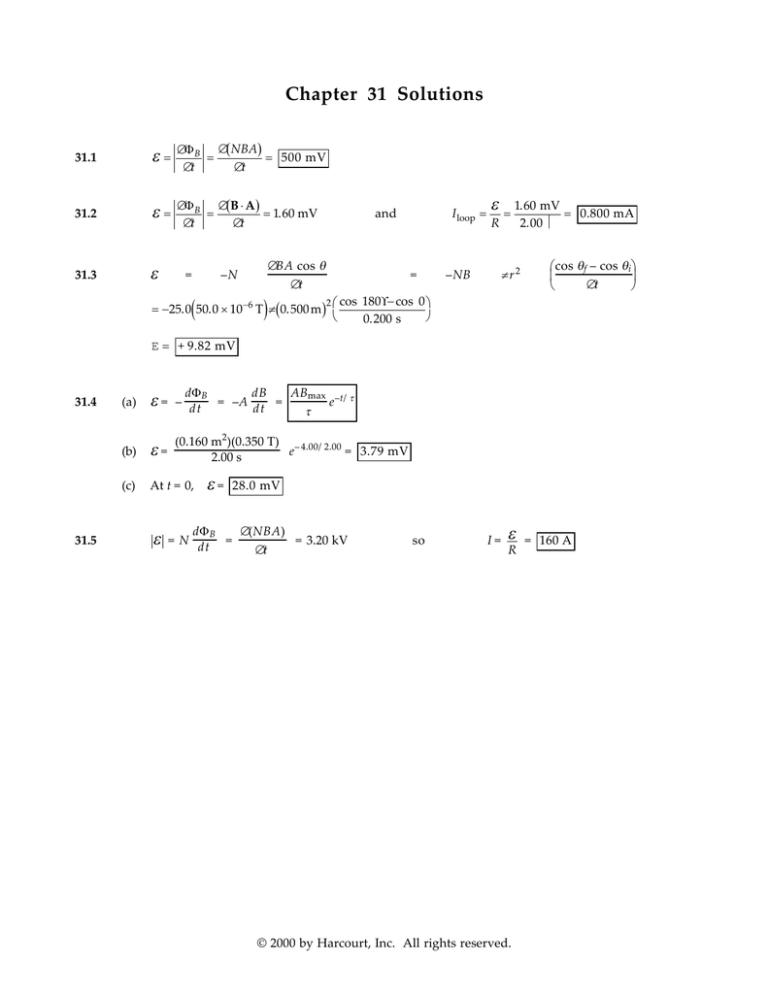
Chapter 31 Solutions 31.1 ε= ∆Φ B ∆( NBA) = = 500 mV ∆t ∆t 31.2 ε= ∆Φ B ∆(B ⋅ A ) = = 1.60 mV ∆t ∆t 31.3 ε = –N ( ∆BA cos θ = ∆t ) = −25.0 50.0 × 10 −6 T π (0.500 m ) I loop = and 2 cos –NB ε = R 1.60 mV = 0.800 mA 2.00 Ω πr2 180° − cos 0 0.200 s cos θf – cos θi ∆t E = + 9.82 mV 31.4 31.5 (a) ε= dΦB dB ABmax –t/ τ – dt = –A dt = e τ (b) ε= (0.160 m2)(0.350 T) – 4.00/2.00 e = 3.79 mV 2.00 s (c) At t = 0, ε ε= 28.0 mV dΦ B ∆(NBA) = N dt = = 3.20 kV ∆t so I= ε R © 2000 by Harcourt, Inc. All rights reserved. = 160 A Chapter 31 Solutions 219 Goal Solution A strong electromagnet produces a uniform field of 1.60 T over a cross-sectional area of 0.200 m 2 . A coil having 200 turns and a total resistance of 20.0 Ω is placed around the electromagnet. The current in the electromagnet is then smoothly decreased until it reaches zero in 20.0 ms. What is the current induced in the coil? G: A strong magnetic field turned off in a short time ( 20.0 ms ) will produce a large emf, maybe on the order of 1 kV . With only 20.0 Ω of resistance in the coil, the induced current produced by this emf will probably be larger than 10 A but less than 1000 A. O: According to Faraday’s law, if the magnetic field is reduced uniformly, then a constant emf will be produced. The definition of resistance can be applied to find the induced current from the emf. A : Noting unit conversions from F = qv × B and U = qV , the induced voltage is ε = −N d(B ⋅ A) = −N 0 − Bi A cos θ = ∆t dt I= ε R = ( ) + 200(1.60 T ) 0.200 m 2 (cos 0°) 1 N ⋅ s / C ⋅ m 1 V ⋅ C 20.0 × 10 −3 s T N ⋅ m = 3200 V 3200 V = 160 A 20.0 Ω L : This is a large current, as we expected. The positive sign is indicative that the induced electric field is in the positive direction around the loop (as defined by the area vector for the loop). ε = –N 31.6 ∆t = ε 31.7 dΦ B N(BA – 0) dt = – ∆t NBA ε = NB( π r 2) ε = 500(0.200)π (5.00 × 10⁻²)2 = 7.85 × 10⁻⁵ s 10.0 × 10³ d(BA) dI = 0.500 µ 0nA dt = 0.480 × 10⁻³ V dt = ε 4.80 × 10-4 = 1.60 A 3.00 × 10⁻⁴ (a) Iring = (b) Bring = (c) Coil's field points downward, and is increasing, so R = µ 0I 2rring = 20.1 µT Bring points upward 31.8 ε = d(BA) dI 2 ∆I = 0.500 µ 0nA dt = 0.500 µ0n π r 2 dt ∆t © 2000 by Harcourt, Inc. All rights reserved. 220 Chapter 31 Solutions ε 2 µ 0 n π r 2 ∆I 2R ∆t (a) Iring = (b) µ 0 n π r2 ∆I µ 0I B = 2r = 4r R 1 1 ∆t (c) The coil's field points downward, and is increasing, so (a) dΦ B = B ⋅ dA = (b) ε= R = 2 31.9 − 2 µ0I Ldx : 2π x ΦB = ∫ h+w µ 0 IL x=h 2π Bring points upward . µ IL h + w dx = 0 ln h 2π x dΦ B d µ IL h + w µ L h + w dI = − 0 ln = − 0 ln dt 2 π h dt 2 π h dt 4 π × 10 ε = −( −7 ) T ⋅ m A (1.00 m ) 2π ln A 1.00 + 10.0 10.0 = s 1.00 − 4.80 µ V The long wire produces magnetic flux into the page through the rectangle (first figure, above). As it increases, the rectangle wants to produce its own magnetic field out of the page, which it does by carrying counterclockwise current (second figure, above). Chapter 31 Solutions 221 31. 10 Φ B = (µ 0nI)Asolenoid 2 2 ε = −N dΦB = −Nµ 0n(π rsolenoid ) dI = −Nµ 0n(π rsolenoid )(600 dt dt ε = −15.0( 4 π × 10−7 )( ) A s) cos(120t) T ⋅ m A 1.00 × 10 3 m π (0.0200 m ) (600 A s) cos(120t) 2 E = −14.2 cos(120t) mV 31.11 For a counterclockwise trip around the left-hand loop, with B = At [ ] d At(2a2 )cos 0° − I1(5R) − I PQ R = 0 dt and for the right-hand loop, [ ] d At a2 + I PQ R − I 2 (3R) = 0 dt where I PQ = I1 − I 2 is the upward current in QP Thus, 2Aa2 − 5R(I PQ + I 2 ) − I PQ R = 0 Aa2 + I PQ R = I 2 (3R) and 2Aa2 − 6RI PQ − 53 (Aa2 + I PQ R) = 0 31.12 ε= I PQ = Aa2 upward, and since R = (0.100 Ω/m)(0.650 m) = 0.0650 Ω 23R I PQ = (1.00 × 10 − 3 T / s)(0.650 m)2 = 283 µA upward 23(0.0650 Ω) ∆Φ B dB A = N (0.0100 + 0.0800t )A =N dt ∆t At t = 5.00 s, ε = 30.0(0.410 T)[π (0.0400 m)2 ] = 61.8 mV © 2000 by Harcourt, Inc. All rights reserved. 222 Chapter 31 Solutions 31.13 ( B = µ 0nI = µ 0n( 30.0 A ) 1 − e −1.60t ) ( Φ B = ∫ B dA = µ 0n( 30.0 A ) 1 − e −1.60t ( )∫ dA ) Φ B = µ 0n( 30.0 A ) 1 − e −1.60t π R 2 ε = − N d ΦB = − Nµ 0n(30.0 A)π R 2 (1.60)e − 1.60t dt ε = −(250)(4 π × 10−7 N A 2 )(400 m −1 )(30.0 A)[π (0.0600 m)2 ]1.60 s−1 e −1.60t ε 31.14 = (68.2 mV )e −1.60t counterclockwise B = µ 0nI = µ 0nI max (1 − e − α t ) Φ B = ∫ B dA = µ 0nI max (1 − e − α t )∫ dA Φ B = µ 0nI max (1 − e − α t )π R 2 ε = − N d ΦB = − Nµ 0nImax π R 2α e − α t dt ε 31.15 = Nµ 0nI max π R 2α e − α t counterclockwise ε= l= Nl2 ∆B cos θ d (NBl2 cos θ ) = dt ∆t ε ∆t N ∆B cos θ = (80.0 × 10 −3 V)(0.400 s) = 1.36 m (50)(600 × 10 −6 T − 200 × 10 −6 T)cos(30.0°) Length = 4 lN = 4(1.36 m)(50) = 272 m Chapter 31 Solutions 223 Goal Solution A coil formed by wrapping 50.0 turns of wire in the shape of a square is positioned in a magnetic field so that the normal to the plane of the coil makes an angle of 30.0° with the direction of the field. When the magnetic field is increased uniformly from 200 µ T to 600 µ T in 0.400 s, an emf of 80.0 mV is induced in the coil. What is the total length of the wire? G: If we assume that this square coil is some reasonable size between 1 cm and 1 m across, then the total length of wire would be between 2 m and 200 m. O: The changing magnetic field will produce an emf in the coil according to Faraday’s law of induction. The constant area of the coil can be found from the change in flux required to produce the emf. A : By Faraday’s law, ε = −N For magnitudes, ε and the area is A= dΦ B d dB = −N (BA cos θ ) = −NA cos θ dt dt dt = NA cos θ ∆B ∆t ε ∆B N cos θ ∆t = 80.0 × 10 −3 V 600 × 10 −6 T − 200 × 10 −6 T 50(cos 30.0°) 0.400 s = 1.85 m 2 Each side of the coil has length d = A , so the total length of the wire is L = N ( 4d) = 4N A = (4)(50) 1.85 m 2 = 272 m L : The total length of wire is slightly longer than we predicted. With d = 1.36 m , a normal person could easily step through this large coil! As a bit of foreshadowing to a future chapter on AC circuits, an even bigger coil with more turns could be hidden in the ground below high-power transmission lines so that a significant amount of power could be “stolen” from the electric utility. There is a story of one man who did this and was arrested when investigators finally found the reason for a large power loss in the transmission lines! 31.16 ∆Φ B ∆t The average induced emf is given by ε Here N = 1, and ∆Φ B = B(Asquare with Acircle = π r 2 = π (0.500 m)2 = 0.785 m 2 = – N − Acircle ) Also, the circumference of the circle is 2π r = 2π (0.500 m) = 3.14 m Thus, each side of the square has a length and So 3.14 m = 0.785 m, 4 Asquare = L2 = 0.617 m 2 L= ∆Φ B = (0.400 T)(0.617 m 2 − 0.785 m 2 ) = − 0.0672 T ⋅ m 2 The average induced emf is therefore: ε=– − 0.0672 T ⋅ m 2 = 0.672 V 0.100 s © 2000 by Harcourt, Inc. All rights reserved. 224 Chapter 31 Solutions In a toroid, all the flux is confined to the inside of the toroid. 31.17 B= µ 0 NI 500 µ 0 I = 2π r 2π r Φ B = ∫ B dA = ΦB = 500 µ 0 I max dz dr sin ω t ∫ 2π r 500 µ 0 I max b + R asin ω t ln R 2π ε = N ′ dΦB = 20 500 µ 0 Imax ω a ln b + R cos ω t dt 2π R rad N ( 3.00 + 4.00) cm 4 π × 10 −7 2 ( 50.0 A ) 377 (0.0200 m)ln cos ω t = (0.422 V) cos ω t s 2π 4.00 cm A ε = 10 31.18 4 N I l The field inside the solenoid is: B = µ 0nI = µ 0 Thus, through the single-turn loop Φ B = BAsolenoid = µ 0 and the induced emf in the loop is ε = − ∆ΦB = −µ 0 N (π r 2 ) ∆I = ε = −N dΦB 31.19 IR = −N dt Idt = − Q=− N dΦ B R ∆t dΦ B dt N ∫ Idt = − R ∫ dΦB ( N N ∆Φ B = − A Bf − Bi R R ) 200 −4 2 Q = − (100 × 10 m )(−1.10 − 1.10) T = 0.880 C 5.00 Ω 31.20 I= ε R = Blv R v = 1.00 m/s l ( ) N π r2 I l ∆t − µ 0 Nπ r 2 I 2 – I1 ∆t l Chapter 31 Solutions 225 31.21 (a) F B = I 1 × B = I lB. FB = When I = E / R and ε = Blv , we get Blv B2l2 v (2.50)2 (1.20)2 (2.00) (lB) = = = 3.00 N R 6.00 R The applied force is 3.00 N to the right (b) P = I 2R = FB = IlB *31.22 I= 31.23 B2l2 v 2 = 6.00 W R E Blv = R R I 2lR lv (a) FB = (b) I 2R = 2.00 W (c) For constant force, or P = Fv = 6.00 W and E = Blv so B= and I= IR lv FB v = 0.500 A R P = F ⋅ v = (1.00 N )( 2.00 m / s) = 2.00 W The downward component of B, perpendicular to v, is (50.0 × 10⁻⁶ T) sin 58.0° = 4.24 × 10⁻⁵ T ( ) E = Blv = 4.24 × 10 −5 T (60.0 m )( 300 m / s) = 0.763 V The left wing tip is positive relative to the right. 31.24 d ε = –N dt ∆A BA cos θ = –NB cos θ ∆t ε = –1(0.100 T) cos 0° I= (3.00 m × 3.00 m sin 60.0°) – (3.00 m)2 = 1.21 V 0.100 s 1.21 V = 0.121 A 10.0 Ω The flux is into the page and decreasing. The loop makes its own magnetic field into the page by carrying clockwise current. 31.25 ω = (2.00 rev/s)(2π rad/rev) = (4.00)π rad/s 1 2 E = Bω l2 = 2.83 mV © 2000 by Harcourt, Inc. All rights reserved. 226 Chapter 31 Solutions 31.26 (a) Bext = Bext i and Bext decreases; therefore, the induced field is B0 = B 0 i (to the right). Therefore, the current is to the right in the resistor. (b) Bext = Bext (–i) increases; therefore, the induced field B0 = B 0 (+ i) is to the right, and the current is to the right in the resistor. (c) (a) (b) (c) (d) Bext = Bext (–k) into the paper and Bext decreases; therefore, the induced field is B0 = B 0 (–k) into the paper. Therefore, the current is to the right in the resistor. (d) By the Lorentz force law, F B = q (v × B). Therefore, a positive charge will move to the top of the bar if B is into the paper . 31.27 (a) The force on the side of the coil entering the field (consisting of N wires) is F = N ( ILB) = N ( IwB) The induced emf in the coil is ε =N d(Bwx ) dΦ B =N = NBwv, dt dt so the current is I = ε R = NBwv R counterclockwise. The force on the leading side of the coil is then: F=N N 2B2 w 2 v NBwv wB = to the left R R Φ B = NBA = constant , so ε = 0, (b) Once the coil is entirely inside the field, . I = 0, and F = 0 (c) As the coil starts to leave the field, the flux decreases at the rate Bwv , so the magnitude of the current is the same as in part (a), but now the current flows clockwise. Thus, the force exerted on the trailing side of the coil is: Chapter 31 Solutions 227 N 2B2 w 2 v to the left again R F= 31.28 (a) Motional emf ε = Bwv appears in the conducting water. Its resistance, if the plates are submerged, is ρL ρw = A ab Kirchhoff's loop theorem says Bwv – IR – I= Bwv R+ (b) 31.29 Iρ w =0 ab ρw ab = abvB abR ρ+ w (100 m)(5.00 m)(3.00 m/s)(50.0 × 10– 6 T) = 0.750 mA 100 Ω · m Isc = Look in the direction of ba. The bar magnet creates a field into the page, and the field increases. The loop will create a field out of the page by carrying a counterclockwise current. Therefore, current must flow from b to a through the resistor. Hence, V a – V b will be negative . 1 2 31.30 E = Bω l2 = 0.259 mV 31.31 Name the currents as shown in the diagram: Left loop: + Bdv2 − I 2 R 2 − I1R 1 = 0 Right loop: + Bdv3 − I 3 R 3 + I1R 1 = 0 At the junction: I 2 = I1 + I 3 Then, Bdv2 − I1R 2 − I 3 R 2 − I1R 1 = 0 I3 = So, Bdv3 I1R 1 + R3 R3 B dv2 − I1 (R 1 + R 2 ) − B dv3 R 2 R3 − I1R 1R 2 R3 =0 © 2000 by Harcourt, Inc. All rights reserved. 228 Chapter 31 Solutions v2 R 3 − v3 R 2 I1 = Bd upward R 1R 2 + R 1R 3 + R 2 R 3 (4.00 m / s)(15.0 Ω) − (2.00 m / s)(10.0 Ω) I1 = (0.0100 T)(0.100 m) (5.00 Ω)(10.0 Ω) + (5.00 Ω)(15.0 Ω) + (10.0 Ω)(15.0 Ω) upward 31.32 (a) dB 2 dt = 6.00t – 8.00t ε F = qE = 8.00 × 10⁻²¹ N 31.33 When 6.00t2 – 8.00t = 0, dB dt = 0.0600t At t = 3.00 s, *31.34 145 µA dΦB dt π R 2(dB/dt) 8.00π (0.0250)2 = 2π r 2 2π (0.0500) At t = 2.00 s, E = (b) = = ε clockwise for electron t = 1.33 s dΦB = dt 2 dB –3 E = π r1 = 1.80 × 10 N/C perpendicular to r1 and counterclockwise 2π r 1 dt ε = dΦB = π r 2 dB = ∫ E ⋅ d1 dt E(2 π R) = π r 2 dt dB , dt or π r 2 dB E= 2 π R dt B = µ 0nI dI dB = µ 0n dt dt I = 3.00 e 0.200t dI = 0.600 e 0.200t dt At t = 10.0 s, becomes E= E= π r2 (µ 0n)(0.600 e 0.200t ) 2π R (0.0200 m)2 (4 π × 10 −7 N / A 2 )(1000 turns / m)(0.600)e 2.00 = 2.23 × 10 −5 N / C 2(0.0500 m) Chapter 31 Solutions 229 31.35 (a) ∫ E ⋅ d1 = dΦ B dt 2 π rE = ( π r 2 ) (b) dB dt so E = (9.87 mV/m) cos (100 π t) The E field is always opposite to increasing B. ∴ clockwise © 2000 by Harcourt, Inc. All rights reserved. 230 Chapter 31 Solutions rev 2π rad 1 min = 314 rad/s For the alternator, ω = 3000 m i n 1 rev 60 s 31.36 ε = −N dΦB = −250 d [(2.50 × 10⁻⁴ T ⋅ m 2 )cos(314 t / s)] = +250(2.50 × 10⁻⁴ T · m2)(314/s) sin(314t) dt dt 31.37 (a) ε = (19.6 V) sin(314t) (b) ε max = 19.6 V (a) εmax = NABω = (1000)(0.100)(0.200)(120π) = (b) ε(t) = –NBAω · sin ωt = –NBAω sin θ ε is maximal when sin θ = 1, 7.54 kV π or θ = ± 2 , so the plane of coil is parallel to B 31.38 Let θ represent the angle through which the coil turns, starting from θ = 0 at an instant when the horizontal component of the Earth's field is perpendicular to the area. Then, ε =− N d d BA cos θ = − NBA cos ω t = + NBAω sin ω t dt dt Here sin ω t oscillates between +1 and –1, so the spinning coil generates an alternating voltage with amplitude ε max = NBAω = NBA2π f 31.39 ( = 100(2.00 × 10 −5 T)(0.200 m)2 (1500) )( 2 π rad = 12.6 mV 60.0 s ) B = µ 0nI = 4 π × 10 −7 T ⋅ m A 200 m −1 (15.0 A ) = 3.77 × 10 −3 T For the small coil, Thus, ( ) Φ B = NB ⋅ A = NBA cos ω t = NB π r 2 cos ω t ε = − dΦB = NBπ r 2ω sin ω t dt ε = (30.0)(3.77 × 10⁻³ T)π (0.0800 m)2 ( 4.00π s−1 ) sin( 4.00π t) = (28.6 mV) sin(4.00π t) Chapter 31 Solutions 231 As the magnet rotates, the flux through the coil varies sinusoidally in time with Φ B = 0 at t = 0. Choosing the flux as positive when the field passes from left to right through the area of the coil, the flux at any time may be written as Φ B = −Φ max sin ω t so the induced emf is given by 31.40 1 0.5 I/I max 0 0 0.5 -1 t/T = ( ω t / 2 π ) dt The current in the coil is then (a) 1.5 -0.5 ε = − dΦB = ω Φ max cos ω t . 31.41 1 I= ε R = ω Φ max cos ω t = I max cos ω t R F = NI lB τmax = 2Fr = NI lwB = 0.640 N · m (b) P = τω = (0.640 N · m)(120π rad/s) 1 P max = 241 W (about 3 hp) 31.42 (a) ε max = BAω = B( 21 π R 2 )ω ε ε max = (1.30 T) π (0.250 m)2 4.00π 2 ε max = (b) (c) rad s Figure 1 1.60 V 2π ε = ∫0 ε 2π dθ = ε BAω 2π 2π ∫0 sin θ dθ = 0 The maximum and average ε would remain unchanged. Figure 2 (d) See Figure 1 at the right. 31.43 (e) See Figure 2 at the right. (a) ΦB = BA cos θ = BA cos ωt = (0.800 T)(0.0100 m2) cos 2π (60.0)t = (8.00 mT · m2) cos (377t) © 2000 by Harcourt, Inc. All rights reserved. 2 232 Chapter 31 Solutions dΦB = (3.02 V) sin (377t) dt (b) ε=– (c) I = ε R = (3.02 A) sin (377t) (d) P = I 2R = (9.10 W) sin2 (377t) (e) P = Fv = τ ω so τ= P = (24.1 mN · m) sin2 (377t) ω At terminal speed, the upward magnetic force exerted o n the lower edge of the loop must equal the weight of the loop. That is, 31.44 Mg = FB = IwB = B2 w 2 vt ε Bwvt wB = wB = R R R Thus, B= (0.150 kg)(9.80 m s2 )(0.750 Ω) = (1.00 m)2 (2.00 m s) 0.742 T See the figure above with Problem 31.44. 31.45 (a) At terminal speed, or *31.46 MgR = w 2 vt vt = Mg = FB = IwB = B2 w 2 vt ε Bwvt wB = wB = R R R MgR B2 w 2 (b) The emf is directly proportional to vt , but the current is inversely proportional to R. A large R means a small current at a given speed, so the loop must travel faster to get Fm = mg. (c) At given speed, the current is directly proportional to the magnetic field. But the force is proportional to the product of the current and the field. For a small B, the speed must increase to compensate for both the small B and also the current, so vt ∝ B2 . The current in the magnet creates an upward magnetic field, so the N and S poles on the solenoid core are shown correctly. On the rail in front of the brake, the upward flux of B increases as the coil approaches, so a current is induced here to create a downward magnetic field. This is clockwise current, so the S pole on the rail is shown correctly. On the rail behind the brake, the upward magnetic flux is decreasing. The induced current in the rail will produce upward magnetic field by being counterclockwise as the picture correctly shows. Chapter 31 Solutions 233 F = ma = qE + qv × B 31.47 e a = [E + v × B] where m a= i v × B = 200 k 0 0 = − 200(0.400)j + 200(0.300)k 0.200 0.300 0.400 1.60 × 10 −19 [50.0j − 80.0j + 60.0k] = 9.58 × 10⁷ [−30.0j + 60.0k] 1.67 × 10 −27 a = 2.87 × 10 9 [−j + 2k] m s 2 = F = ma = qE + qv × B so 31.48 j (−2.87 × 10 9 j + 5.75 × 10 9 k) m s 2 −e a = [E + v × B] m i where j k v × B = 10.0 0 0 = − 4.00j 0 0 0.400 a= (−1.60 × 10 ) [2.50i + 5.00 j − 4.00 j] = (−1.76 × 10 )[2.50i + 1.00 j] 9.11 × 10 a= (− 4.39 × 10 −19 11 −31 11 ) i − 1.76 × 10¹¹ j m s 2 ε = −N d (BA cos θ ) = −N (π r 2 ) cos 0˚ dB dt dt *31.49 ε = − (30.0)π (2.70 × 10⁻³ m) (1) d [50.0 mT + (3.20 mT) sin (2π dt 2 ε = − (30.0)π (2.70 × 10⁻³ m) ε= *31.50 (a) ( 2 (3.20 × 10 T)(2π )(523 s) cos (2π 523t −3 ) − 7.22 × 10 −3 V cos ( 2 π 523t s) Doubling the number of turns. Amplitude doubles: period unchanged (b) Doubling the angular velocity. doubles the amplitude: cuts the period in half (c) Doubling the angular velocity while reducing the number of turns to one half the original value. Amplitude unchanged: cuts the period in half ] 523t s) © 2000 by Harcourt, Inc. All rights reserved. s) 234 Chapter 31 Solutions T ε = −N ∆ (BA cos θ ) = −N (π r 2 ) cos 0˚ ∆B = −1(0.00500 m 2 )(1) 1.50 T − 5.00 = 0.875 V −3 ∆t ∆t *31.51 31.52 20.0 × 10 ε 0.875 V = 43.8 A 0.020 0 Ω (a) I= (b) P = EI = (0.875 V )( 43.8 A ) = 38.3 W R = s In the loop on the left, the induced emf is ε = dΦ B dB 2 =A = π (0.100 m ) (100 T s) = π V dt dt and it attempts to produce a counterclockwise current in this loop. In the loop on the right, the induced emf is ε = dΦ B 2 = π (0.150 m ) (100 T s) = 2.25 π V dt and it attempts to produce a clockwise current. Assume that I1 flows down through the 6.00-Ω resistor, I 2 flows down through the 5.00-Ω resistor, and that I 3 flows up through the 3.00-Ω resistor. From Kirchhoff’s point rule: I 3 = I1 + I 2 (1) Using the loop rule on the left loop: 6.00 I1 + 3.00I 3 = π (2) Using the loop rule on the right loop: 5.00 I 2 + 3.00I 3 = 2.25 π (3) Solving these three equations simultaneously, I1 = 0.0623 A , *31.53 I 2 = 0.860 A , and I 3 = 0.923 A The emf induced between the ends of the moving bar is ε = Blv = (2.50 T)(0.350 m)(8.00 m s) = 7.00 V The left-hand loop contains decreasing flux away from you, so the induced current in it will be clockwise, to produce its own field directed away from you. Let I1 represent the current flowing upward through the 2.00-Ω resistor. The right-hand loop will carry counterclockwise current. Let I 3 be the upward current in the 5.00-Ω resistor. Chapter 31 Solutions 235 (a) (b) Kirchhoff’s loop rule then gives: +7.00 V − I1 ( 2.00 Ω) = 0 I1 = 3.50 A and +7.00 V − I 3 ( 5.00 Ω) = 0 I 3 = 1.40 A The total power dissipated in the resistors of the circuit is P = EI1 + EI 3 = E( I1 + I 3 ) = (7.00 V )( 3.50 A + 1.40 A ) = 34.3 W (c) Method 1: The current in the sliding conductor is downward with value I 2 = 3.50 A + 1.40 A = 4.90 A . The magnetic field exerts a force of Fm = IlB = ( 4.90 A )(0.350 m )( 2.50 T ) = 4.29 N directed toward the right on this conductor. A n outside agent must then exert a force of 4.29 N to the left to keep the bar moving. Method 2: The agent moving the bar P = F ⋅ v = Fv cos 0˚ . The force required is then: F= *31.54 must supply the power according to P 34.3 W = = 4.29 N v 8.00 m s Suppose we wrap twenty turns of wire into a flat compact circular coil of diameter 3 cm. Suppose we use a bar magnet to produce field 10 −3 T through the coil in one direction along its axis. Suppose we then flip the magnet to reverse the flux in 10 −1 s. The average induced emf is then ε = − N ∆ΦB = − N ∆[BA cos θ ] = −NB(π r 2 ) cos180˚ − cos 0˚ ∆t ∆t ε = − (20)(10−3 T)π (0.0150 m)2 31.55 I= ε + ε Induced R and ∆t −2 10 −1 s ~10 − 4 V d ε Induced = – dt (BA) dv F = m dt = IBd dv IBd Bd Bd dt = m = m R (ε + ε Induced) = m R (ε – Bvd) To solve the differential equation, let u = (ε – Bvd), 1 du Bd – Bd dt = m R u ∫u so Integrating from t = 0 to t = t, e −B u 0 du dv dt = –Bd dt . t du (Bd)2 = −∫ dt t=0 u mR u ln u 0 (Bd)2 = – mR u0 = ε and u = ε – Bvd t 2 2 d t/mR Since v = 0 when t = 0, © 2000 by Harcourt, Inc. All rights reserved. or u u0 = 236 Chapter 31 Solutions ε – Bvd = ε e −B d t/mR 2 2 and v= ε Bd (1 − e −B 2 2 d t/mR ) Chapter 31 Solutions 237 31.56 (a) For maximum induced emf, with positive charge at the top of the antenna, F+ = q+ (v × B), so the auto must move east (b) 31.57 65.0 × 10³ m cos 65.0° = 4.58 × 10– 4 V = (5.00 × 10⁻⁵ T)(1.20 m) 3600 s ε = Blv I= ε = R B ∆A R ∆t q = I ∆t = so (15.0 µ T)(0.200 m)2 = 1.20 µC 0.500 Ω Goal Solution The plane of a square loop of wire with edge length a = 0.200 m is perpendicular to the Earth's magnetic field at a point where B = 15.0 µ T , as shown in Figure P31.57. The total resistance of the loop and the wires connecting it to the galvanometer is 0.500 Ω. If the loop is suddenly collapsed by horizontal forces as shown, what total charge passes through the galvanometer? G: For the situation described, the maximum current is probably less than 1 mA. So if the loop is closed in 0.1 s, then the total charge would be Q = I∆t = (1 mA )(0.1 s) = 100 µ C O: We do not know how quickly the loop is collapsed, but we can find the total charge by integrating the change in magnetic flux due to the change in area of the loop ( a2 → 0). A: Q = ∫ Idt = ∫ ε dt R = A2 =0 B Q = − A R A 1 =a = 2 1 1 1 B d ΦB − d ΦB = − d(BA) = − dt = − dt R R R R ∫ ∫ ∫ ∫ A2 =0 A1 =a 2 dA Ba2 (15.0 × 10 −6 T)(0.200 m)2 = = 1.20 × 10 −6 C R 0.500 Ω L : The total charge is less than the maximum charge we predicted, so the answer seems reasonable. It is interesting that this charge can be calculated without knowing either the current or the time to collapse the loop. Note: We ignored the internal resistance of the galvanometer. D’Arsonval galvanometers typically have an internal resistance of 50 to 100 Ω, significantly more than the resistance of the wires given in the problem. A proper solution that includes RG would reduce the total charge by about 2 orders of magnitude ( Q ~ 0.01 µ C). © 2000 by Harcourt, Inc. All rights reserved. 238 Chapter 31 Solutions *31.58 (a) dq ε I = dt = R E = −N where dΦ B dt so and the charge through the circuit will be (b) 31.59 31.60 N π BAN = BA cos 0 − BA cos 2 R R so B= RQ NA = (200 Ω)(5.00 × 10– 4 C) (100)(40.0 × 10– 4 m 2 ) ε Q = N R Φ2 ∫ dΦB Φ1 N (Φ2 – Φ1) R = 0.250 T (a) ε = B lv = 0.360 V (b) FB = IlB = 0.108 N (c) Since the magnetic flux B · A is in effect decreasing, the induced current flow through R is from b to a. Point b is at higher potential. (d) N o . Magnetic flux will increase through a loop to the left of ab. Here counterclockwise current will flow to produce upward magnetic field. The in R is still from b to a. I= R = 0.900 A ε = Blv at a distance r from wire ε 31.61 Q= ∫ dq = (a) µ I = 0 lv 2π r At time t , the flux through the loop is At t = 0, Φ B = π ar 2 (b) ε = − dΦB = − π r 2 d( a + bt) = (c) I= (d) π br 2 π 2b 2 r 4 2 P = ε I = − π br = − R R dt ε R = − dt − π br 2 π br 2 R ( ) ( ) Φ B = BA cos θ = ( a + bt) π r 2 cos 0˚ = π ( a + bt)r 2 Chapter 31 Solutions 239 ε = − d (NBA) = −1 dB π a2 = π a2 K 31.62 dt dt (a) (b) Q = C ε = C π a2K B into the paper is decreasing; therefore, current will attempt to counteract this. charge will go to upper plate . (c) The changing magnetic field through the enclosed area Positive induces an electric field , surrounding the B-field, and this pushes on charges in the wire. The flux through the coil is Φ B = B ⋅ A = BA cos θ = BA cos ω t . The induced emf is 31.63 d cos ω t ) ε = − N dΦB = − NBA ( = NBAω sin ω t. dt dt (a) ε max = NBAω = 60.0(1.00 T)(0.100 × 0.200 m 2 )(30.0 (b) dΦ B ε = , dt N (c) thus dΦ B dt = max ε max = 36.0 V = 0.600 V = N At t = 0.0500 s, ω t = 1.50 rad and (d) The torque on the coil at any time is When 31.64 (a) We use ε = ε max , sin ω t = 1.00 and ε =– N rad s) = 36.0 V 60.0 0.600 Wb/s ε = ε max sin(1.50 rad) = (36.0 V) sin(1.50 rad) = 35.9 V ε ε τ = µ × B = NIA × B = ( NAB) I sin ω t = max sin ω t ω R τ= 2 ε max = ωR (36.0 V )2 = (30.0 rad s)(10.0 Ω) 4.32 N · m ∆Φ B , with N = 1. ∆t Taking a = 5.00 × 10- 3 m to be the radius of the washer, and h = 0.500 m, µ0I 1 µ I a2µ 0 I 1 − µ 0 ahI − = ∆Φ B = B2 A − B1A = A(B2 − B1 ) = π a2 − 0 = h + a a 2 2(h + a) 2 π (h + a) 2 π a ∆t = The time for the washer to drop a distance h (from rest) is: (b) Therefore, ε= µ 0 ahI µ 0 ahI = 2(h + a)∆t 2(h + a) and ε= ( 4π × 10 −7 T ⋅ m/A)( 5.00 × 10 −3 m)(10.0 A) 2(0.500 m + 0.00500 m) g µ 0 aI = 2h 2(h + a) 2h g gh 2 (9.80 m/s 2 )(0.500 m) = 97.4 nV 2 Since the magnetic flux going through the washer (into the plane of the paper) is decreasing in time, a current will form in the washer so as to oppose that decrease. Therefore, the current will flow in a clockwise direction . © 2000 by Harcourt, Inc. All rights reserved. 240 Chapter 31 Solutions 31.65 ε = −N dΦB = −N d (BA cos θ ) dt dt ∆t 31.66 Find an expression for the flux through a rectangular area "swept out" by the bar in time t. The magnetic field at a distance x from wire is B= µ0I and ΦB = ∫ BdA. 2π x ΦB = µ 0 Ivt 2π Then, 31.67 −4 m2 = –10.2 µV 1.80 s ε = −NBcos θ ∆A = − 200(50.0 × 10− 6 T)(cos 62.0˚ ) 39.0 × 10 r+l ∫ dx x = µ 0 Iv l dΦ B = ln 1 + 2π dt r r ε Therefore, where vt is the distance the bar has moved in time t. The magnetic field at a distance x from a long wire is B = µ0I . 2π x Find an expression for the flux through the loop. dΦ B = µ0I (ldx) 2π x Therefore, 31.68 ΦB = µ 0 Il 2π r+w ∫ r w dx µ 0 Il = ln 1 + 2π r x ε = − dΦB = µ 0 Ilv dt w 2 π r (r + w) and I= ε R = µ 0 Ilv w 2 π Rr (r + w) As the wire falls through the magnetic field, a motional emf ε = Blv is induced in it. Thus, a The falling wire counterclockwise induced current of I = ε R = Blv R flows in the circuit. is carrying a current toward the left through the magnetic field. Therefore, it experiences an upward magnetic force given by FB = IlB = B2l2 v R. The wire will have attained terminal speed when the magnitude of this magnetic force equals the weight of the wire. Thus, 31.69 so mgR B2l2 vt = mg , or the terminal speed is vt = R B2l2 ΦB = (6.00t 3 – 18.0t 2) T · m2 Maximum and ε occurs when dε dt ε=– dΦB 2 dt = –18.0t + 36.0t = – 36.0t + 36.0 = 0, which gives t = 1.00 s. Therefore, the maximum current (at t = 1.00 s) is I= ε R = (–18.0 + 36.0)V = 6.00 A 3.00 Ω Chapter 31 Solutions 241 ΣF = Mg – T = Ma For the suspended mass, M: 31.70 ΣF = T – I lB = ma, where I = For the sliding bar, m: Mg − v ∫0 B2l2 v = (m + M)a R t dv = ∫ dt 0 (α − β v) ε = –N R = Blv R or a= Mg dv B2l2 v = − dt m + M R(M + m) where α= Mg M+m v= Therefore, the velocity varies with time as *31.71 (a) ε β= and B2l2 R(M + m) 2 2 MgR α (1 − e −β t ) = 1 − e −B l t/R(M+m) 2 2 β Bl dΦ B dB d dt = –NA dt = –NA dt (µ 0nI) where A = area of coil, N = number of turns in coil, and n = number of turns per unit length in solenoid. Therefore, (b) ε d = Nµ 0 An dt [ 4 sin(120π t)] = Nµ 0An(480π ) cos (120π t) ε = 40(4π × 10–7 ) π (0.0500 m)2 (2.00 × 10³)(480π) cos(120π t) = (1.19 V) cos(120π t) [ ∆V I= R and P = ∆VI From cos2 θ = 31.72 ] = (1.19 V)2 cos2(120π t) (8.00 Ω) 1 1 1 2 2 + 2 cos 2θ, the average value of cos θ is 2 , so The induced emf is ε = Blv where ( B= P= ( 1 (1.19 V ) = 88.5 mW 2 (8.00 Ω) 2 ) µ0I , v = vi + gt = 9.80 m s 2 t , and 2π y ) y = yi − 21 gt 2 = 0.800 m − 4.90 m s 2 t 2 . ε= (4π × 10 −7 [ ) T ⋅ m A ( 200 A ) ( ) ] 2 π 0.800 m − 4.90 m s 2 t 2 At t = 0.300 s , ε= ( ) (0.300 m) 9.80 m s 2 t = (1.18 × 10 )(0.300) (1.18 × 10 )t −4 [0.800 − 4.90t ] −4 [ 0.800 − 4.90(0.300) 2 ] V = 98.3 µV © 2000 by Harcourt, Inc. All rights reserved. 2 V 242 Chapter 31 Solutions 31.73 The magnetic field produced by the current in the straight wire is perpendicular to the plane of the coil at all points within the coil. The magnitude of the field is B = µ 0 I 2 π r . Thus, the flux linkage is NΦ B = µ 0 NIL h+w dr µ 0 NI max L h + w sin(ω t + φ ) = ln h 2π ∫ h 2π r Finally, the induced emf is ε = −( ε= ) ε = − µ 0 NImax Lω ln 1 + w cos(ω t + φ ) 2π 4 π × 10 −7 (100)(50.0)(0.200 m)(200 π s −1 ) 2π h 5.00 cm cos(ω t + φ ) ln 1 + 5.00 cm − (87.1 mV ) cos(200 π t + φ ) The term sin(ω t + φ )in the expression for the current in the straight wire does not change appreciably when ω t changes by 0.100 rad or less. Thus, the current does not change appreciably during a time interval t< 0.100 = 1.60 × 10 − 4 s . (200 π s −1 ) ct = (3.00 × 10⁸ m / s)(1.60 × 10 −4 s) = 4.80 × 10 4 m equal to the We define a critical length, distance to which field changes could be propagated during an interval of 1.60 × 10 −4 s. This length is so much larger than any dimension of the coilor its distance from the wire that, although we consider the straight wire to be infinitely long, we can also safely ignore the field propagation effects in the vicinity of the coil. Moreover, the phase angle can be considered to be constant along the wire in the vicinity of the coil. If the frequency ω were much larger, say, 200 π × 10 5 s −1 , the corresponding critical length would be only 48.0 cm. In this situation propagation effects would be important and the above expression for ε would require modification. As a "rule of thumb" we can consider field propagation effects for circuits of laboratory size to be negligible for frequencies, f = ω 2 π , that are less than about 106 Hz. 31.74 ΦB = BA cos θ dΦB dt = –ω BA sinθ ; I ∝ – sin θ τ ∝ IB sin θ ∝ – sin2 θ 31.75 The area of the tent that is effective in intercepting magnetic field lines is the area perpendicular to the direction of the magnetic field. This is the same as the base of the tent. In the initial configuration, this is A1 = L(2L cos θ ) = 2(1.50 m)2 cos 60.0˚ = 2.25 m 2 After the tent is flattened, A2 = L(2L) = 2L2 = 2(1.50 m)2 = 4.50 m 2 The average induced emf is: ε = − ∆ΦB = − B( ∆A) = − ( ∆t ∆t 0.300 T )( 4.50 − 2.25) m 2 = – 6.75 V 0.100 s
