Power Supply Design Checklist - System Reliability Center
advertisement

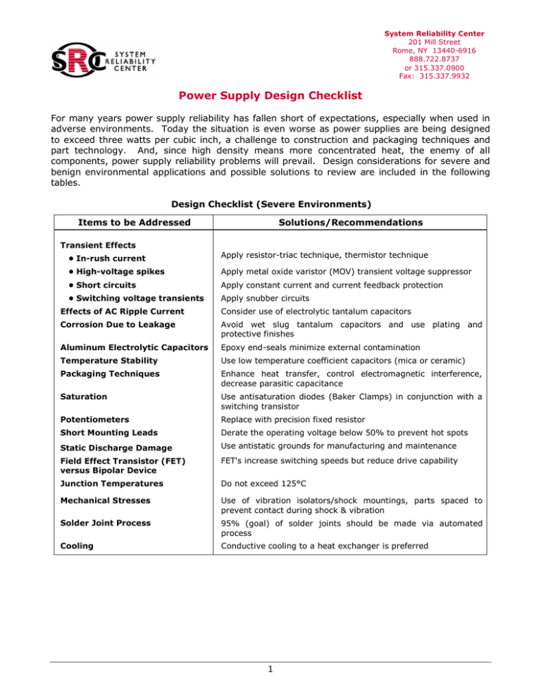
System Reliability Center 201 Mill Street Rome, NY 13440-6916 888.722.8737 or 315.337.0900 Fax: 315.337.9932 Power Supply Design Checklist For many years power supply reliability has fallen short of expectations, especially when used in adverse environments. Today the situation is even worse as power supplies are being designed to exceed three watts per cubic inch, a challenge to construction and packaging techniques and part technology. And, since high density means more concentrated heat, the enemy of all components, power supply reliability problems will prevail. Design considerations for severe and benign environmental applications and possible solutions to review are included in the following tables. Design Checklist (Severe Environments) Items to be Addressed Solutions/Recommendations Transient Effects • In-rush current Apply resistor-triac technique, thermistor technique • High-voltage spikes Apply metal oxide varistor (MOV) transient voltage suppressor • Short circuits Apply constant current and current feedback protection • Switching voltage transients Apply snubber circuits Effects of AC Ripple Current Consider use of electrolytic tantalum capacitors Corrosion Due to Leakage Avoid wet slug tantalum capacitors and use plating and protective finishes Aluminum Electrolytic Capacitors Epoxy end-seals minimize external contamination Temperature Stability Use low temperature coefficient capacitors (mica or ceramic) Packaging Techniques Enhance heat transfer, control electromagnetic interference, decrease parasitic capacitance Saturation Use antisaturation diodes (Baker Clamps) in conjunction with a switching transistor Potentiometers Replace with precision fixed resistor Short Mounting Leads Derate the operating voltage below 50% to prevent hot spots Static Discharge Damage Use antistatic grounds for manufacturing and maintenance Field Effect Transistor (FET) versus Bipolar Device FET's increase switching speeds but reduce drive capability Junction Temperatures Do not exceed 125°C Mechanical Stresses Use of vibration isolators/shock mountings, parts spaced to prevent contact during shock & vibration Solder Joint Process 95% (goal) of solder joints should be made via automated process Cooling Conductive cooling to a heat exchanger is preferred 1 System Reliability Center 201 Mill Street Rome, NY 13440-6916 888.722.8737 or 315.337.0900 Fax: 315.337.9932 Power Supply Design Checklist (Cont'd) Design Checklist (Benign Environments) Items to be Addressed Solutions/Recommendations Vendor selects best commercial practice parts Part Quality Vendor selects screened industrial grade parts Unit Quality Vendor burns-in all units at higher temperatures Part Derating Vendor has in-house standards Electrical Parameters Vendor values exceed needs at temperature extremes Failure Analysis Vendor has failure tracking program Protection Circuits Vendor has built-in voltage and current sensors Fault Flags Vendor has built-in failure indicators Reliability Experience Successful operation in similar environments Copyright 2001 Alion Science and Technology. All rights reserved. Source: • RAC Publication, CPE, Reliability Toolkit: Commercial Practices Edition. For More Information: • Rome Laboratory Report, 1991, RL-TR-91-39, "Power Supply Fault Tolerant Reliability Study." • Department of the Navy Report, 1989, NAVMAT P-4855, "Navy Power Supply Reliability – Design Manufacturing Guidelines." • Wright Laboratory Report, 1988, AFWAL TR-88-4143, "Applying AVIP to High Voltage Power Supply Designs." 2

