Single Stage DC-AC Boost Converter
advertisement
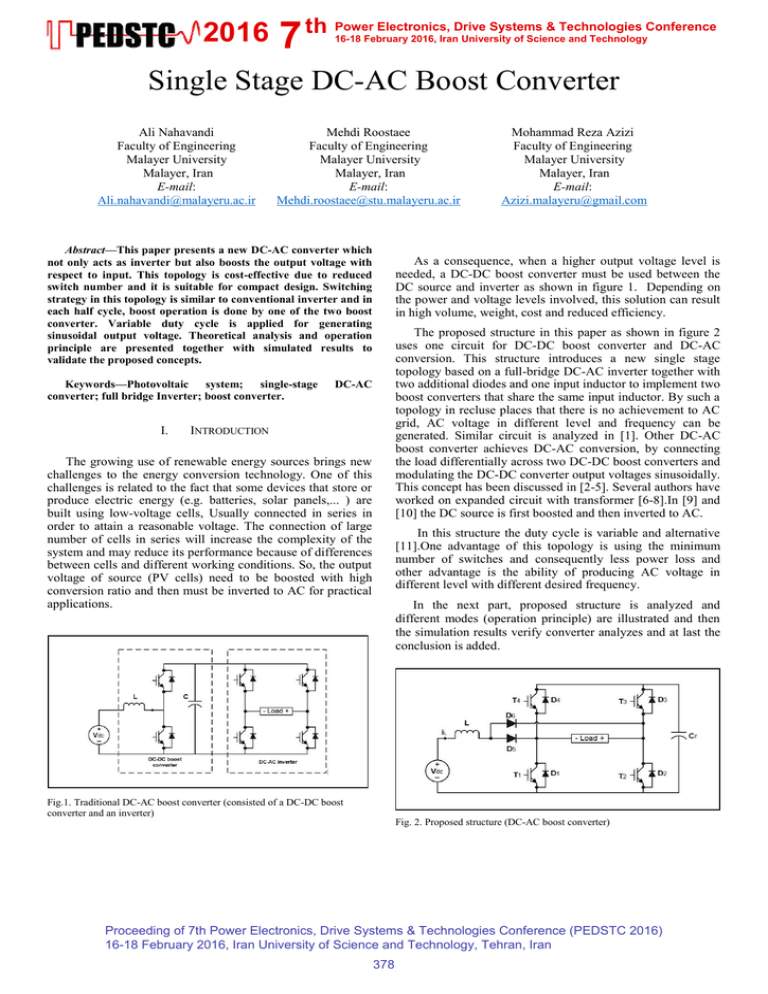
2016 7 th Power Electronics, Drive Systems & Technologies Conference 16-18 February 2016, Iran University of Science and Technology Single Stage DC-AC Boost Converter Ali Nahavandi Faculty of Engineering Malayer University Malayer, Iran E-mail: Ali.nahavandi@malayeru.ac.ir Mehdi Roostaee Faculty of Engineering Malayer University Malayer, Iran E-mail: Mehdi.roostaee@stu.malayeru.ac.ir Abstract—This paper presents a new DC-AC converter which not only acts as inverter but also boosts the output voltage with respect to input. This topology is cost-effective due to reduced switch number and it is suitable for compact design. Switching strategy in this topology is similar to conventional inverter and in each half cycle, boost operation is done by one of the two boost converter. Variable duty cycle is applied for generating sinusoidal output voltage. Theoretical analysis and operation principle are presented together with simulated results to validate the proposed concepts. Keywords—Photovoltaic system; single-stage converter; full bridge Inverter; boost converter. I. Mohammad Reza Azizi Faculty of Engineering Malayer University Malayer, Iran E-mail: Azizi.malayeru@gmail.com As a consequence, when a higher output voltage level is needed, a DC-DC boost converter must be used between the DC source and inverter as shown in figure 1. Depending on the power and voltage levels involved, this solution can result in high volume, weight, cost and reduced efficiency. The proposed structure in this paper as shown in figure 2 uses one circuit for DC-DC boost converter and DC-AC conversion. This structure introduces a new single stage topology based on a full-bridge DC-AC inverter together with two additional diodes and one input inductor to implement two boost converters that share the same input inductor. By such a topology in recluse places that there is no achievement to AC grid, AC voltage in different level and frequency can be generated. Similar circuit is analyzed in [1]. Other DC-AC boost converter achieves DC-AC conversion, by connecting the load differentially across two DC-DC boost converters and modulating the DC-DC converter output voltages sinusoidally. This concept has been discussed in [2-5]. Several authors have worked on expanded circuit with transformer [6-8].In [9] and [10] the DC source is first boosted and then inverted to AC. DC-AC INTRODUCTION The growing use of renewable energy sources brings new challenges to the energy conversion technology. One of this challenges is related to the fact that some devices that store or produce electric energy (e.g. batteries, solar panels,... ) are built using low-voltage cells, Usually connected in series in order to attain a reasonable voltage. The connection of large number of cells in series will increase the complexity of the system and may reduce its performance because of differences between cells and different working conditions. So, the output voltage of source (PV cells) need to be boosted with high conversion ratio and then must be inverted to AC for practical applications. In this structure the duty cycle is variable and alternative [11].One advantage of this topology is using the minimum number of switches and consequently less power loss and other advantage is the ability of producing AC voltage in different level with different desired frequency. In the next part, proposed structure is analyzed and different modes (operation principle) are illustrated and then the simulation results verify converter analyzes and at last the conclusion is added. Fig.1. Traditional DC-AC boost converter (consisted of a DC-DC boost converter and an inverter) Fig. 2. Proposed structure (DC-AC boost converter) Proceeding of 7th Power Electronics, Drive Systems & Technologies Conference (PEDSTC 2016) 16-18 February 2016, Iran University of Science and Technology, Tehran, Iran 378


