Dimensioning: is the process of defining the size, form and location
advertisement

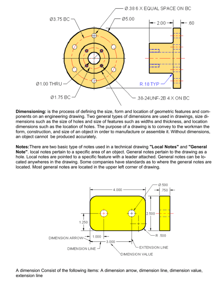
Dimensioning: is the process of defining the size, form and location of geometric features and components on an engineering drawing. Two general types of dimensions are used in drawings, size dimensions such as the size of holes and size of features such as widths and thickness, and location dimensions such as the location of holes. The purpose of a drawing is to convey to the workman the form, construction, and size of an object in order to manufacture or assemble it. Without dimensions, an object cannot be produced accurately. Notes:There are two basic type of notes used in a technical drawing "Local Notes" and "General Note". local notes pertain to a specific area of an object. General notes pertain to the drawing as a hole. Local notes are pointed to a specific feature with a leader attached. General notes can be located anywheres in the drawing. Some companies have standards as to where the general notes are located. Most general notes are located in the upper left corner of drawing. A dimension Consist of the following items: A dimension arrow, dimension line, dimension value, extension line A location dimension locates holes or other part features. A size dimension gives of radius, diameters, lengths, widths and thickness. Different styles of dimensioning may be applied to a drawing, depending on the company you work for, they also called company drawing standards. The most commonly used dimension styles are set forth in the ansi standard. The examples in this book are applied using the ansi standard. A leader dimension is a leader line used to point toward a diameter or radius. A diameter dimension is a dimension that specifies a diameter of a circle. A radius dimension is used to specify a radius. A angular dimension is used to specify the amount of degrees between two lines that are parallel or colinear to each other A linear dimension is a dimension that is either horizontal or a vertical to the dimensioning plane Tabular Dimensions - When a company manufactures a family of parts or assemblies that are exactly alike in shape except for dimensions , tabular dimensioning is used on a drawing. Letters and numbers in a tabular from are used instead of dimensions to denote size. Coordinate Dimensions - Coordinate dimensioning is used on prints that would require many dimension and extension lines. Coordinate dimensioning helps to keep the drawing from becoming difficult to read. This type of dimensioning is frequently used on prints of parts to be machined by numerical control. Dual Dimensioning: Working drawing are usually drawn with all U.S. or all metric Dimensions. Sometimes the object manufactured using both U.S. and metric measuring system. Dual dimensioning may be necessary. When the object is to be manufactured is both measuring systems a combination of both U.S and metric dimensions are present. Hole dimensions are used to denote drilled hole information by use a leader line pointing toward center of the hole. There are basicly three types of dimensioning systems use in creating prints they are as follows: U.S System: ASME standards for the U.S dimensioning use the decimal inch values. When the decimal inch system is used, a zero is not used to the left of the decimal point for values less than one inch. The same number of decimal places should be used for dimensions and tolerancing. Metric Dimensioning: ASME standards for the use of metric dimensioning require all the dimensions to be expressed in millimeters (mm). The (mm) is not needed on each dimension, but it is used when a dimension is used in a notation. Zeros precedes decimal point when the value is less than one millimeters. Dual Dimensioning: Working drawing are usually drawn with all U.S. or all metric Dimensions. Sometimes the object manufactured using both U.S. and metric measuring system. Dual dimensioning may be necessary. When the object is to be manufactured is both measuring systems a combination of both U.S and metric dimensions are present. Metric Dimensioning: ASME standards for the use of metric dimensioning require all the dimensions to be expressed in millimeters (mm). The (mm) is not needed on each dimension, but it is used when a dimension is used in a notation. Zeros precedes decimal point when the value is less than one millimeters. Dual Dimensioning: Working drawing are usually drawn with all U.S. or all metric Dimensions. Sometimes the object manufactured using both U.S. and metric measuring system. Dual dimensioning may be necessary. When the object is to be manufactured is both measuring systems a combination of both U.S and metric dimensions are present. U.S System: ASME standards for the U.S dimensioning use the decimal inch values. When the decimal inch system is used, a zero is not used to the left of the decimal point for values less than one inch. The same number of decimal places should be used for dimensions and tolerancing. Notes on a drawing provide added data and information not found in the views but for the part to be completed. Notes should be read first before studying the views of the parts because they may advise you of certain requirements regarding the part. There are two kinds of notes "local Notes" and "general Notes"


