5300 series relief valves.
advertisement
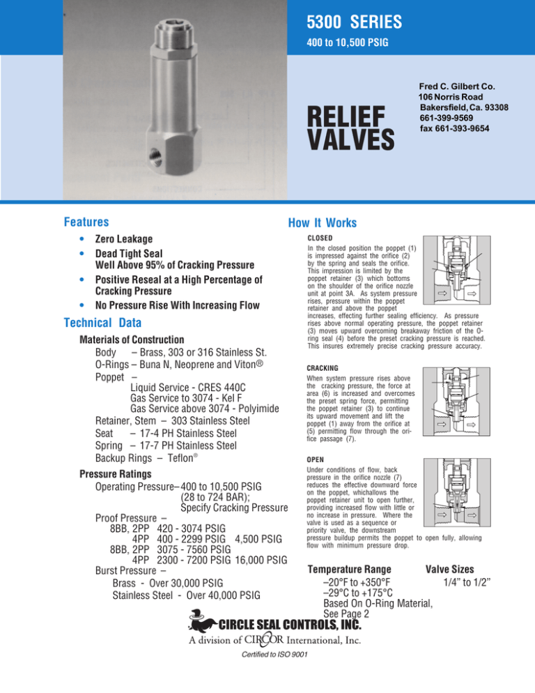
5300 SERIES 400 to 10,500 PSIG RELIEF VALVES Features • • • • Fred C. Gilbert Co. 106 Norris Road Bakersfield, Ca. 93308 661-399-9569 fax 661-393-9654 How It Works Zero Leakage Dead Tight Seal Well Above 95% of Cracking Pressure Positive Reseal at a High Percentage of Cracking Pressure No Pressure Rise With Increasing Flow CLOSED In the closed position the poppet (1) is impressed against the orifice (2) by the spring and seals the orifice. This impression is limited by the poppet retainer (3) which bottoms on the shoulder of the orifice nozzle unit at point 3A. As system pressure rises, pressure within the poppet retainer and above the poppet increases, effecting further sealing efficiency. As pressure rises above normal operating pressure, the poppet retainer (3) moves upward overcoming breakaway friction of the Oring seal (4) before the preset cracking pressure is reached. This insures extremely precise cracking pressure accuracy. Technical Data Materials of Construction Body – Brass, 303 or 316 Stainless St. O-Rings – Buna N, Neoprene and Viton® Poppet – Liquid Service - CRES 440C Gas Service to 3074 - Kel F Gas Service above 3074 - Polyimide Retainer, Stem – 303 Stainless Steel Seat – 17-4 PH Stainless Steel Spring – 17-7 PH Stainless Steel Backup Rings – Teflon® Pressure Ratings Operating Pressure– 400 to 10,500 PSIG (28 to 724 BAR); Specify Cracking Pressure Proof Pressure – 8BB, 2PP 420 - 3074 PSIG 4PP 400 - 2299 PSIG 4,500 PSIG 8BB, 2PP 3075 - 7560 PSIG 4PP 2300 - 7200 PSIG 16,000 PSIG Burst Pressure – Brass - Over 30,000 PSIG Stainless Steel - Over 40,000 PSIG CRACKING When system pressure rises above the cracking pressure, the force at area (6) is increased and overcomes the preset spring force, permitting the poppet retainer (3) to continue its upward movement and lift the poppet (1) away from the orifice at (5) permitting flow through the orifice passage (7). OPEN Under conditions of flow, back pressure in the orifice nozzle (7) reduces the effective downward force on the poppet, whichallows the poppet retainer unit to open further, providing increased flow with little or no increase in pressure. Where the valve is used as a sequence or priority valve, the downstream pressure buildup permits the poppet to open fully, allowing flow with minimum pressure drop. Certified to ISO 9001 Temperature Range Valve Sizes –20°F to +350°F 1/4” to 1/2” –29°C to +175°C Based On O-Ring Material, See Page 2 5300 SERIES 400 to 10,500 PSIG How To Order L 53 49 B - 4 PP (L) - 500 CRACKING PRESSURE Specify cracking pressure setting in PSIG. 500 - 500 PSIG VARIATION L - For All Liquid Service BASIC MODEL NUMBER 5300 Series SPECIAL CHARACTERISTICS (L) - Lockwire O-RING MATERIAL & TEMPERATURE 49 - Buna N -20°F to +250°F 33 - Neoprene -20°F to +240°F -20°F to +350°F 32 - Viton® CONNECTIONS P - Female Pipe B - Female Tube, AND10050 J - Female Tube, MS33649 K - British Parallel Pipe (Male) L - British Parallel Pipe (Female) G - Aminco, Union V - NASA MC240 BODY MATERIAL B - Brass T - 303 Stainless Steel T1 - 316 Stainless Steel VALVE SIZE (Pipe Sizes in 1/8”-Increments; Tube Sizes in 1/16”-Increments) 4 - 1/2” Notes: Back Pressure – Any back pressure above atmosphere reduces the cracking pressure by .35 psi for each 1.0 psi of back pressure. Cracking Pressure – Valves are preset at factory. Pressure at which valves will crack in normal service, cracking pressure = 5%. Leakage at Reseal Pressure – Air - Zero; Liquid - 5 Drops/Min. (Max.) Teflon® is a registered trademark of DuPont and Viton® is a registered trademark of DuPont Dow Elastomers. Please consult your Circle Seal Controls Distributor, Representative or our factory for information on special connections, O-rings, operating pressures and temperature ranges. Cracking Pressure Setting • Range • Replacement Spring Number Dash No. Port Size C.P. Setting C.P. Range Spring Number 4PP 1/2” 500 700 1000 1500 2000 3000 5000 8000 400 - 700 550 - 950 850 - 1350 1250 - 2000 1650 - 2700 1900 - 3500 3100 - 7200 4000 - 10,500 A565-100 A565-140 A565-200 A565-300 A565-400 A575-500 A575-1000 575-910 2PP 8BB 1/4” 1/2” 500 700 1000 1400 1700 2200 2800 3500 5800 8000 420 - 600 575 - 850 825 - 1190 1170 - 1650 1500 - 2075 1710 - 2570 2300 - 3120 3030 - 4100 3890 - 7560 4000 - 10,500 535-70 535-100 535-140 535-200 535-250 535-300 535-400 545-500 545-850 545-1030 5300-8BB, 5300-2PP – Springs in the 420-3074 psi range are interchangeable and springs in the 307510,500 psi range are interchangeable. 5300-4PP – Springs in the 400-2299 psi range are interchangeable and springs in the 230010,500 psi range are interchangeable. 5300 SERIES 400 to 10,500 PSIG Reseal Characteristics CRACKING PRESSURE Standard Seals . . . . . . . . . 5 cc/min. with gas Teflon® . . . . . . . . . . . . . . . . . . . 0.02 cc/min. scfm or valves with C.P. over 450 psi The point at which the valve closes, cutting off virtually all flow, is called the reseal point. The reseat point is substantially above reseal. Replacement Parts In normal service the only parts which may require replacement are the O-rings. A complete Repair Kit may be ordered. See table on previous page for replacement springs. Dimensions C H B G D K Orifice Dia. Inlet Outlet E Outlet Inlet F Pipe C.P. Range (PSI) Size 1/4”420-3074 1/4”3075-10,500 1/2”400-2299 1/2”2300-10,500 B Max. 4.88 5.78 7.01 8.48 C Hex. 1/2 3/8 9/16 1/2 D 3.83 3.83 5.67 5.67 E .52 .52 .82 .82 F Hex. 1.50 1.50 2.00 2.00 G Dia. 1.38 1.38 1.75 1.75 H Hex. 1.25 1.25 1.50 1.50 K Dia. .125 .125 .188 .188 Weight (lbs.) Brass 303 S.S. 1.6 1.5 1.8 1.7 3.2 3.0 3.7 3.5 Tube C.P. Range (PSI) Size 1/2”420-3074 1/2”3075-10,500 B Max. 4.88 5.78 C Hex. 1/2 3/8 D 4.59 4.59 E .70 .70 F Hex. 1.875 1.875 G Dia. 1.38 1.38 H Hex. 1.25 1.25 K Dia. .125 .125 Weight (lbs.) Brass 303 S.S. 1.6 1.5 1.8 1.7 Dimensions in inches. 5300 SERIES 400 to 10,500 PSIG Typical Flow Curves Pressure Drop 5300-4PP with HYDRAULIC FLUID Pressure Drop Flow GPM 5300-BB, 5300-2PP with HYDRAULIC FLUID Pressure Drop Flow SCFM Pressure Drop Flow GPM Flow SCFM Increasing Flow Decreasing Flow Certified to ISO 9001 CSC-496-L • 4/97
