Servo Motors - Alfred State College intranet site
advertisement
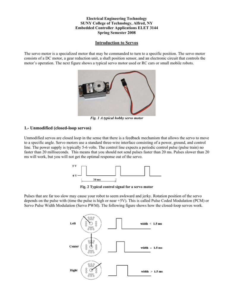
Electrical Engineering Technology SUNY College of Technology, Alfred, NY Embedded Controller Applications ELET 3144 Spring Semester 2008 Introduction to Servos The servo motor is a specialized motor that may be commanded to turn to a specific position. The servo motor consists of a DC motor, a gear reduction unit, a shaft position sensor, and an electronic circuit that controls the motor’s operation. The next figure shows a typical servo motor used or RC cars or small mobile robots. Fig. 1 A typical hobby servo motor 1.- Unmodified (closed-loop servos) Unmodified servos are closed loop in the sense that there is a feedback mechanism that allows the servo to move to a specific angle. Servo motors use a standard three-wire interface consisting of a power, ground, and control line. The power supply is typically 5-6 volts. The control line expects a periodic control pulse (pulse train) no faster than 20 milliseconds. This means that you should not send pulses faster than 20 ms. Pulses slower than 20 ms will work, but you will not get the optimal response out of the servo. Fig. 2 Typical control signal for a servo motor Pulses that are far too slow may cause your robot to seem awkward and jerky. Rotation position of the servo depends on the pulse with (time the pulse is high or near +5V). This is called Pulse Coded Modulation (PCM) or Servo Pulse Width Modulation (Servo PWM). The following figure shows how the closed-loop servos work. Fig. 3 Control signals to position the servo in a specific position Depending on the manufacturer, the range of the pulse width to drive the servo varies. In general, typical values are in the ranges: 0.9 ms to 1.5 ms to move to the left, 1.5 ms in the center, 1.5 ms to 2.1 ms to move to the right. 2.- Modified (open-loop servos) Modified servos are modified so that they can turn freely forever. There is no way of determining how far they have traveled, or making them only to turn to a certain angle since the feedback mechanism has been removed. One main advantage of this type of servos is that it can be used to drive a robot wheel continuously while controlling both speed and direction. Open-loop servos are similar to closed-loop in that they turn one direction or the other depending on the pulse that are given. Open-loop servos expect a periodic control pulse of 20 ms just as close-loop servos. The main difference is that the feedback mechanism stopping the servo from “moving to far” has been removed The speed of the servo depends on how much more or how much less the pulse with is compared to a “STOP” pulse. Here the STOP pulse stops the servo from moving rather that moving to the CENTER position. By varying the pulse widths, you can vary the speed. The following figure shows how the open-loop servos work. Fig. 3 Control signals to rotate the servo in a specific direction If a servo is driving the wheel of a mobile robot, you can measure the rotational speed or get the manufacturer rated rotational speed. Using this rotational speed and the diameter of the wheel, you can calculate the distance the robot travels Distance S = π ω D where S is the distance traveled in one minute (cm) D is diameter of the wheel (cm) ω is the angular velocity of the servo measured in Revolutions Per Minute (RPM) Using a Modified Servomotor to control a mobile robot using the 68HC11 Most hobby servo motors use a standard three-wire interface consisting of a power, ground , and control line. The power supply is typically 5-6 volts. The control signal uses a train of pulses, and depending on the length of the positive-going pulse, will be the speed and direction of the motor. Typical pulse width values to control the motor in clockwise (CW) and counterclockwise(CCW) directions are given in Fig. 4. Fig. 4 Typical Servo Motor Pulse Width Position Signals To generate the waveforms required to control the servo motor using the 68HC11, the Output Compare Register and the Free Running Counter (TCNT) available in the 68HC11 can be used. The following programs show how to control a servo motor using the 68HC11. Program 1. Driving the servo motor in clockwise direction. ; Using the OC2 (PA6) to generate a train of pulses to drive a servomotor clockwise (CW) ; The period of the signal is around 17 msec ; The length of the positive-going control pulse is around 2msec (2000us) TCTL1 EQU $1020 TFLG1 EQU $1023 TOC2 EQU $1018 ORG $2000 LDS $3000 LDX #TFLG1 AGAIN LDAA #%10000000 ; Set OM2=1 and 0L2=0 in TCTL1 to clear OC2(PA6) on successful compare STAA TCTL1 LDAA #%01000000 ; Reset OC2F in TFLG1 STAA 0,X LOOP1 BRCLR 0,X $40 LOOP1 ; Wait until OC2F sets and toggle the output ; BRCLR performs a logical AND of the memory location specified ; and the mask supplied with the instruction, and branches if ; the result is zero ; Set the lenght of the zero level control pulse to 15 msec LDD TOC2 ; Get present TOC2 value ADDD #30000 ; Add 300000 and store it back (30000 x 0.5 us = 15 msec) STD TOC2 LDAA #%11000000 ; Set OM2=1 and 0L2=1 in TCTL1 to set OC2(PA6) on successful compare STAA TCTL1 LDAA #%01000000 ; Reset OC2F in TFLG1 STAA 0,X LOOP2 BRCLR 0,X $40 LOOP2 ; Wait until OC2F sets and toggle the output ; Set the lenght of the positive-going control pulse to 2 msec LDD TOC2 ; Get present TOC2 value ADDD #4000 ; Add 4000 and store it back (4000 X 0.5 us = 2 ms) STD TOC2 ; The total duration of the signal is: Duration in zero level + Positive-going ("1")=15ms+2ms=17ms BRA AGAIN Program 2. Driving the servo motor in counterclockwise direction. Using the OC2 (PA6) ; The period of the ; The length of the TCTL1 EQU TFLG1 EQU TOC2 EQU ORG LDS LDX AGAIN LDAA compare STAA LDAA STAA LOOP1 BRCLR to generate a train of pulses to drive a servomotor counterclockwise (CCW) signal is around 16 msec positive-going control pulse is around 1 msec (1000us) $1020 $1023 $1018 $2000 $3000 #TFLG1 #%10000000 ; Set OM2=1 and 0L2=0 in TCTL1 to clear OC2(PA6) on successful TCTL1 #%01000000 0,X 0,X $40 LOOP1 ; Reset OC2F in TFLG1 ; Wait until OC2F sets and toggle the output ; BRCLR performs a logical AND of the memory location specified ; and the mask supplied with the instruction, and branches if ; the result is zero ; Set the lenght of the zero level control pulse to 15 msec LDD TOC2 ; Get present TOC2 value ADDD #30000 ; Add 300000 and store it back (30000 x 0.5 us = 15 msec) STD TOC2 LDAA #%11000000 ; Set OM2=1 and 0L2=1 in TCTL1 to set OC2(PA6) on successful compare STAA TCTL1 LDAA #%01000000 ; Reset OC2F in TFLG1 STAA 0,X LOOP2 BRCLR 0,X $40 LOOP2 ; Wait until OC2F sets and toggle the output ; Set the lenght of the positive-going control pulse to 1 msec LDD TOC2 ; Get present TOC2 value ADDD #2000 ; Add 2000 and store it back (2000 X 0.5 us = 1 ms) STD TOC2 ; The total duration of the signal is: Duration in zero level + Positive-going ("1")=15ms+1ms=16ms BRA AGAIN
