Thevenin`s theorem Thevenin`s theorem states: The current through
advertisement
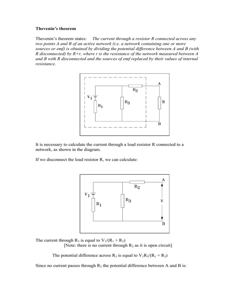
Thevenin’s theorem Thevenin’s theorem states: The current through a resistor R connected across any two points A and B of an active network (i.e. a network containing one or more sources or emf) is obtained by dividing the potential difference between A and B (with R disconnected) by R+r, where r is the resistance of the network measured between A and B with R disconnected and the sources of emf replaced by their values of internal resistance. It is necessary to calculate the current through a load resistor R connected to a network, as shown in the diagram. If we disconnect the load resistor R, we can calculate: The current through R3 is equal to V1/(R1 + R3) [Note: there is no current through R2 as it is open circuit] The potential difference across R3 is equal to V1R3/(R1 + R3) Since no current passes through R2 the potential difference between A and B is: V = V1R3/(R1 + R3) We now have to calculate the resistance r of the network with the sources of emf removed and replaced by their internal resitances (R1 in this example): r = R2 + R1R3/(R1 + R3) We can now redraw our circuit consisting of an emf source of value V and an internal resistance r: Hence: The current through R is = I = V/(r + R) EXAMPLE: A and B are two terminals of an active network. Calculate the current through the load resistor R3 Step 1. With R3 disconnected we can calculate I1 and hence the potential difference between points A and B: I1 = (6 - 4)/(2 + 3) = 0.4 A The p.d. between A and B is V1 - I1R1 = 6 - (0.4 x 2) = 5.2 V Step 2. Remove the emf’s and calculate the equivalent resistance of the circuit The total resistance of the circuit is: 1/r = 1/R1 + 1/R2 = 1/2 + 1/3 = (2 + 3)/2x3 = 5/6 r = 6/5 = 1.2Ω The network can therefore be replaced by a single source of 5.2 V and an internal resistance of 1.2 Ω. Step 3. The current I through the load resistor can now be calculated: I = 5.2/(1.2 + 10) = 0.464 A ELECTRICAL MEASUREMENT Introduction A wide range of analogue instruments are used to take electrical measurements. They are generally cheap to manufacture and are extremely robust. Although the instrument may now contain a digital display, the measuring devices are still based on analogue electronics. The indicating analogue measuring device contains three essential features: a) A deflecting device: a mechanical force is produced by the current, voltage or power. b) A controlling device: the value of the deflection is dependent on the magnitude of the quantity being measured. c) A damping device: to prevent oscillation of the moving system and allow it to reach its final value quickly. POTENTIOMETER This is one of the most useful instruments for measuring potential difference, current and resistance. Measuring potential difference The principle action is that an unknown potential difference is measured by balancing it against a known potential difference. The slider is moved along a uniform wire (connected across a known potential difference) until the deflection in the galvanometer is zero. Using Kirchoff’s second law we find: for loop 1: for loop 2: V0 - (i-i1)R1 - iR2 = 0 VU - (i-i1)R1 = 0 As no current flows through the galvanometer then I1 must be zero. V0 - iR1 - iR2 = 0 VU - iR1 = 0 1. 2. Dividing 2. by 1. and rearranging we get: Vu/V0 = R1/(R1+ R2) or if the wire is uniform then the resistance is proportional to the length, and so: Vu/V0 = L1/(L1+ L2) WHEATSTONE BRIDGE This is used to measure unknown resistance’s. If R3 is adjusted until the current i3 through the galvanometer is zero then using Kirchoff’s law we get: Loop 1: Loop 2: (i1 - i2)R2 - i2R1 = 0 (i1 - i2)Rx - i2R3 = 0 1. 2. Divide 1. by 2. and rearrange: R2/Rx = R1/ R3 If there is no current passing through the galvanometer then the potential difference at either end of the galvanometer must be the same and therefore the potential difference across R1 = the potential difference across R2 = the potential difference across R3 = the potential difference across Rx. GALVANOMETER/AMMETER/VOLTMETER The galvanometer measures current and it relies on the fact that torque is produced on a coil when it is placed in a magnetic field and a current flows through it. If we consider a single turn of the coil PQ with P having the current coming out of the paper and Q having it going in to the paper, then P sets up a magnetic field in the counter clockwise direction, while Q sets up a field in the clockwise direction. The effect of the field produced by P is to strengthen the overall field on P’s lower side, while the field due to Q strengthens the field on Q’s upper side. This therefore distorts the flux from the permanent magnet. As the flux behaves as if it were in tension, it exerts a force F on P and Q which is proportional to the applied current. The deflection of the coil is therefore a measure of the current. The torque is proportional to the (Current x flux density) = kI for uniform flux k is a constant associated with the instrument The torque is also proportional to the angular deflection θ = cθ c is the controlling spring constant Therefore kI = cθ - the deflection is proportional to the current This instrument, due to its delicate nature, is only suitable for measuring currents up to approximately 50 mA. When a larger current is to be measured, a shunt resistance S of low value is connected in parallel with the moving coil. To use the galvanometer as a voltmeter, the shunt resistance is connected in series with it. EXAMPLE: A moving coil galvanometer has an internal resistance of 5 Ω and gives a full scale deflection when 15 mA is applied across it. Calculate the shunt resistance required to: a. b. a. enable the galvanometer to read up to 1A enable the galvanometer to measure up to 10V Current through the coil = p.d. across the coil/resistance of the coil 15x10-3 = p.d/5 p.d. = 0.075V The current through the shunt = Total current - current through the coil = 1 - 15x10-3 = 0.985A Resistance of the shunt S = p.d. across S/current through S = 0.075/0.985 S = 0.07616Ω b. Current through coil = p.d across galvanometer and shunt/the total resistance 15x10-3 = 10/total resistance Total resistance = 666.7Ω The shunt is in series with the galvanometer, therefore: Resistance of the shunt S = 666.7 - 5 S = 661.7Ω

