Technical Data Electrical Symbols and
advertisement

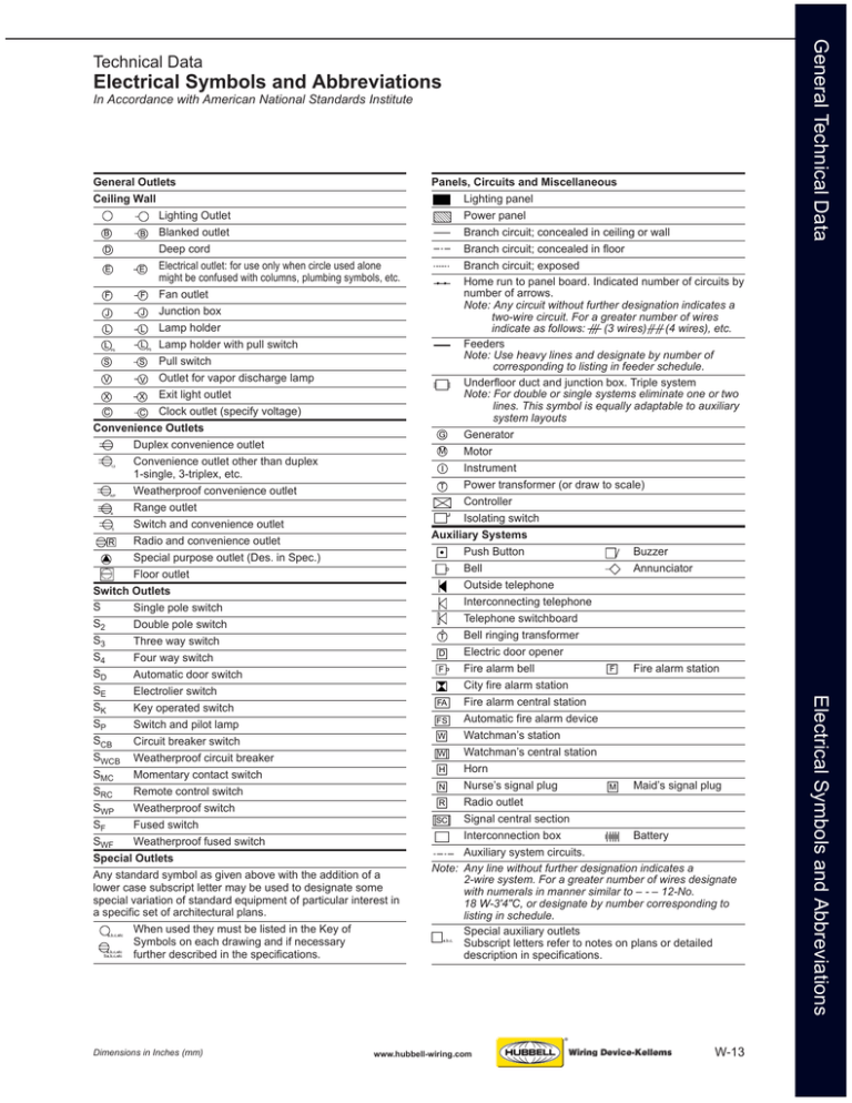
Electrical Symbols and Abbreviations In Accordance with American National Standards Institute PS PS 1,3 WP R S a,b,c,etc a,b,c,etc Sa,b,c,etc Dimensions in Inches (mm) Panels, Circuits and Miscellaneous Lighting panel Power panel Branch circuit; concealed in ceiling or wall Branch circuit; concealed in floor Branch circuit; exposed Home run to panel board. Indicated number of circuits by number of arrows. Note: Any circuit without further designation indicates a two-wire circuit. For a greater number of wires indicate as follows: (3 wires) (4 wires), etc. Feeders Note: Use heavy lines and designate by number of corresponding to listing in feeder schedule. Underfloor duct and junction box. Triple system Note: For double or single systems eliminate one or two lines. This symbol is equally adaptable to auxiliary system layouts G Generator M Motor I Instrument Power transformer (or draw to scale) T Controller Isolating switch Auxiliary Systems Push Button Buzzer Bell Annunciator Outside telephone Interconnecting telephone Telephone switchboard Bell ringing transformer T Electric door opener D F Fire alarm bell Fire alarm station F City fire alarm station FA Fire alarm central station Automatic fire alarm device FS Watchman’s station W Watchman’s central station W Horn H Nurse’s signal plug Maid’s signal plug N M Radio outlet R Signal central section SC Interconnection box Battery Auxiliary system circuits. Note: Any line without further designation indicates a 2-wire system. For a greater number of wires designate with numerals in manner similar to – - – 12-No. 18 W-3'4"C, or designate by number corresponding to listing in schedule. Special auxiliary outlets Subscript letters refer to notes on plans or detailed description in specifications. a,b,c, www.hubbell-wiring.com W-13 Electrical Symbols and Abbreviations General Outlets Ceiling Wall Lighting Outlet Blanked outlet B B Deep cord D Electrical outlet: for use only when circle used alone E E might be confused with columns, plumbing symbols, etc. F F Fan outlet Junction box J J Lamp holder L L L L Lamp holder with pull switch S S Pull switch Outlet for vapor discharge lamp V V Exit light outlet X X C Clock outlet (specify voltage) C Convenience Outlets Duplex convenience outlet Convenience outlet other than duplex 1-single, 3-triplex, etc. Weatherproof convenience outlet Range outlet Switch and convenience outlet Radio and convenience outlet R Special purpose outlet (Des. in Spec.) Floor outlet Switch Outlets S Single pole switch S2 Double pole switch S3 Three way switch S4 Four way switch SD Automatic door switch SE Electrolier switch SK Key operated switch SP Switch and pilot lamp SCB Circuit breaker switch SWCB Weatherproof circuit breaker SMC Momentary contact switch SRC Remote control switch SWP Weatherproof switch SF Fused switch SWF Weatherproof fused switch Special Outlets Any standard symbol as given above with the addition of a lower case subscript letter may be used to designate some special variation of standard equipment of particular interest in a specific set of architectural plans. When used they must be listed in the Key of Symbols on each drawing and if necessary further described in the specifications. General Technical Data Technical Data
