RESISTIVITY Objective Objective of this lab work is to measure
advertisement
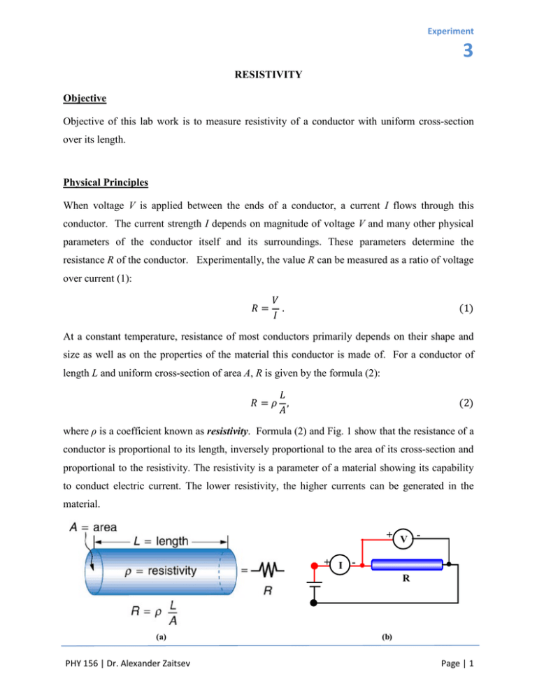
Experiment 3 RESISTIVITY Objective Objective of this lab work is to measure resistivity of a conductor with uniform cross-section over its length. Physical Principles When voltage V is applied between the ends of a conductor, a current I flows through this conductor. The current strength I depends on magnitude of voltage V and many other physical parameters of the conductor itself and its surroundings. These parameters determine the resistance R of the conductor. Experimentally, the value R can be measured as a ratio of voltage over current (1): 𝑅= 𝑉 . 𝐼 (1) At a constant temperature, resistance of most conductors primarily depends on their shape and size as well as on the properties of the material this conductor is made of. For a conductor of length L and uniform cross-section of area A, R is given by the formula (2): 𝐿 𝑅=𝜌 , 𝐴 (2) where ρ is a coefficient known as resistivity. Formula (2) and Fig. 1 show that the resistance of a conductor is proportional to its length, inversely proportional to the area of its cross-section and proportional to the resistivity. The resistivity is a parameter of a material showing its capability to conduct electric current. The lower resistivity, the higher currents can be generated in the material. + V + I R (a) PHY 156 | Dr. Alexander Zaitsev (b) Page | 1 Resisitivity Fig. 1. (a) A conductor of cylindrical shape has length L and area of cross-section A. Since crosssection is uniform over the whole length of this conductor, its resistance can be found using formula (2). (b) R can be found experimentally by measuring the voltage V across the conductor and current I flowing through the conductor under this voltage. Experimentally, resistivity of a conductor can be found by measuring its resistance and its dimensions. If a piece of wire of length L and diameter D is used as the conductor (Fig. 1), its resistivity can be calculated using formula (3): 𝑅𝜋𝐷2 𝜌= . 4𝐿 (3) The voltmeter-ammeter method is used to measure resistance: R = V/I (see manual of the lab work “Ohm’s Law and Resistance”). Thus, the final formula for the calculation of resistivity, ρ is as shown below in formula (4): 𝜌= 𝑉𝜋𝐷2 , 4𝐼𝐿 (4) where V is the voltage applied to the wire and I is the current flowing through the wire under this voltage. In order to understand the relationship between the factors in the formulas above try this interactive applet: http://phet.colorado.edu/sims/resistance-in-a-wire/resistance-in-a-wire_en.html Apparatus ­ Variable DC power supply ­ Wire resistor (R) ( D = 0.64mm) ­ Digital voltmeter (V) ­ Digital ammeter (A) ­ 500 Ω tubular ballast resistor (Ro) ­ Connecting wires PHY 156 | Dr. Alexander Zaitsev Page | 2 Resisitivity Procedure 1. Set up the equipment shown in Fig 2a: Power supply for Vo, the 500 Ω tubular resistor for ballast resistor Ro, digital voltmeter for V, digital ammeter for I, the wire resistor for R. Have your connections checked by your instructor/technician before turning on the power supply. (a) A DC Power Supply mA Ro V A + - 400mA + Vo - V DC mV + - + 100cm 0cm R (b) Fig. 2. (a) Experimental set-up used for the measurement of resistivity using voltmeter-ammeter method (Procedure 1). (b) Scheme of the set-up. Fixing the movable contact on the wire resistor at the 100 cm mark, vary voltage on power supply in 1V steps taking reading of ammeter I and voltmeter V for each voltage step. PHY 156 | Dr. Alexander Zaitsev Page | 3 Resisitivity 2. Set voltage on the power supply, Vo to 10V. Record the current I, which will remain constant thereafter. By means of the movable connector (red connector from the voltmeter) measure voltage V for different lengths L of the wire by tapping the wire at points 1cm to 100cm in 10 cm steps (Fig. 3). (a) A DC Power Supply mA Ro V A + - 400mA + Vo - V DC mV + - + 100cm 0cm R (b) Fig. 3. (a) Experimental set-up used for the measurement of resistivity varying the length of the conductor (Procedure 2). (b) Scheme of the set-up. PHY 156 | Dr. Alexander Zaitsev Page | 4 Resisitivity Calculations 1. From the data of Procedure 1, plot the data using voltage V as ordinate and current I as abscissa (Fig. 4). Fit the experimental points with a straight line passing through the origin. Calculate slope of this line ∆V/∆I. The obtained value is the total resistance R of the wire: R = ∆V/∆I. Using formula (3), calculate resistivity of the metal the wire is made. Slope = ∆V =R ∆I ∆V ∆I Fig. 4. Voltage across the wire as a function of current passing through it (current-voltage characteristic of the wire). Slope of this dependence equals resistance of the wire. 2. From the data of Procedure 2, compute R in ohms, for each length L using formula R = V/I (Fig. 5). Watch the units! Voltage must be taken in Volts, whereas current in Amperes. Plot R as a function of L (R as ordinate and L is abscissa). Fit the experimental points with a straight line passing through the origin. Calculate slope of this line ∆R/∆L. PHY 156 | Dr. Alexander Zaitsev Page | 5 Resisitivity Slope = ∆VR =R ∆∆LI ∆R ∆L Fig. 5. Resistance of the wire as a function of its length. Slope of this dependence equals ratio of resistance over area of cross-section of the wire. Using the value of the slope, calculate resistivity of the wire as a product of slope times area of the wire cross-section (5). 𝜌 = (𝑆𝑙𝑜𝑝𝑒)×𝐴. (5) 3. Compare the values of resistivity obtained in Procedures 1 and 2. Calculate average of these two values and percentage difference between them. Identify the material the wire is made of by comparing the value of resistivity you have measured with the known resistivities of different metals (Table of Resistivities). Questions 1. What role does the ballast resistor R0 play in the circuit used this lab work? 2. Based on the value of resistivity you calculated, what is the material the wire resistor is made of? PHY 156 | Dr. Alexander Zaitsev Page | 6 Resisitivity 3. Is the wire resistor an ohmic conductor? Support your answer with the experimental data you obtained. 4. Do resistance and resistivity depend on: - the wire length? - the wire cross-section? - the wire shape? 5. How could you determine the sign of the thermal coefficient of resistivity of the wire using the given experimental set up? Table 1. Resistivity of Some Common Materials Material Resistivity ρ ( Ω⋅m ) Silver 1.59×10⁻⁸ Copper 1.72×10⁻⁸ Gold 2.44×10⁻⁸ Aluminum 2.65×10⁻⁸ Tungsten 5.6×10⁻⁸ Iron 9.71×10⁻⁸ Platinum 1.06×10⁻⁷ Steel 2×10⁻⁷ Lead 2.2×10⁻⁷ Manganin (Cu, Mn, Ni alloy) 4.4×10⁻⁷ Constantan (Cu, Ni alloy) 4.9×10⁻⁷ Mercury 9.6×10⁻⁷ Nichrome (Ni, Fe, Cr alloy) 1×10⁻⁶ Graphite (pure) 3.5×10⁵ Carbon (3.5−60)×105 Germanium (pure) 0.6 Germanium (1−600)×10−3 Silicon (pure) 2300 Silicon 0.1–2300 Amber 5×10¹⁴ Glass 109−1014 Lucite >1013 Mica 1011−1015 Quartz (fused) 7.5×10¹⁵ Rubber (hard) 1013−1016 Sulfur 1015 Teflon >1013 Wood 108−1011 PHY 156 | Dr. Alexander Zaitsev Page | 7
