The finite-element method
advertisement

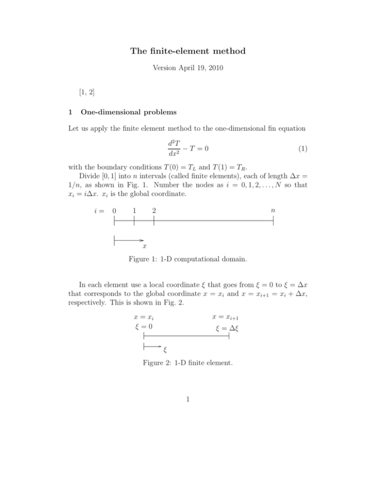
The finite-element method Version April 19, 2010 [1, 2] 1 One-dimensional problems Let us apply the finite element method to the one-dimensional fin equation d2 T −T =0 dx2 (1) with the boundary conditions T (0) = TL and T (1) = TR . Divide [0, 1] into n intervals (called finite elements), each of length ∆x = 1/n, as shown in Fig. 1. Number the nodes as i = 0, 1, 2, . . . , N so that xi = i∆x. xi is the global coordinate. i= 0 1 n 2 x Figure 1: 1-D computational domain. In each element use a local coordinate ξ that goes from ξ = 0 to ξ = ∆x that corresponds to the global coordinate x = xi and x = xi+1 = xi + ∆x, respectively. This is shown in Fig. 2. x = xi+1 x = xi ξ=0 ξ = ∆ξ ξ Figure 2: 1-D finite element. 1 Let us use the linear interpolation functions N1 (ξ) = 1 − N2 (ξ) = ξ ∆x ξ ∆x (2a) (2b) within element i. Notice that (a) N1 (ξ) + N2 (ξ) = 1 and (b) N1 (0) = N2 (∆x) = 1 and N1 (∆x) = N2 (0) = 0. Thus, we can write T (ξ) = Ti−1 N1 (ξ) + Ti N2 (ξ), (3) where Ti−1 = Tx=xi−1 = Tξ=0 and Ti = Tx=xi = Tξ=∆x . Using the Galerkin method Z ∆x 2 dT − T Nk (ξ) dξ = 0, (4) dξ 2 0 where k = 1, 2. Integrating by parts ∆x Z ∆x dT dNk ′ T Nk − + T Nk dξ = 0. dξ dξ 0 0 where T ′ = dT /dξ. Substituting Eq. (3) in the above and carrying out the integrations, we have the two equations 1 ∆x ∆x 1 ′ + Ti = 0, + − −Ti−1 − Ti−1 ∆x 3 ∆x 6 1 ∆x ∆x 1 ′ − Ti = 0, − + Ti + Ti−1 ∆x 6 ∆x 3 for k = 1 and k = 2, respectively. Doing this for each of the N element, (and 2 multiplying by −∆x for convenience) we end up with 2N algebraic equations. ∆x2 )T0 − (1 − 3 ∆x2 )T0 + (1 + −∆x T1′ − (1 − 6 ∆x2 ∆x T1′ + (1 + )T1 − (1 − 3 ∆x2 )T1 + (1 + −∆x T2′ − (1 − 6 ∆x T0′ + (1 + 2 ∆x )TN −1 − (1 − 3 ∆x2 )TN −1 + (1 + −∆x TN′ − (1 − 6 ∆x TN′ −1 + (1 + ∆x2 )T1 6 ∆x2 )T1 3 ∆x2 )T2 6 ∆x2 )T2 3 =0 (5) =0 (6) =0 (7) =0 (8) .. . (9) 2 ∆x )TN = 0 6 ∆x2 )TN = 0 3 (10) (11) There are 2N unknowns including T and T ′ at each of the N + 1 node minus the values of T0 and TN at the two ends that are known, so that we can solve for the unknowns at this stage if we wish. However, it can be noticed that adding Eqs. (6) and (7) cancels the T1′ term. So we discard the first and last equations, add the rest in pairs to get the reduced set c T T c1 −c2 0 ... 0 2 L 1 −c2 c1 −c2 0 . . . 0 T 2 0 −c2 c1 −c2 . . . . .. . (12) = . . .. .. .. .. .. . 0 TN −2 . . . . cT T 0 0 . . . −c c 2 1 N −1 2 R where c1 = 2(1 + ∆x2 /3), c2 = 1 − ∆x2 /6. Example Solve a linear equation of the type d2 T + f (x)T = g(x) dx2 (13) with the boundary conditions T (0) = TL and T (1) = TR . Divide the region into elements, and within each assume that the function can be expanded as Eq. (3), where N1 and N2 are given by Eq. (2). The global coordinate 3 is x, and the local is ξ; they are related by xi = x − xi , where xi is the value of x at the left end of the element. According to the Galerkin method, the residual d2 T + f (x)T − g(x) dx2 should be made orthogonal to N1 and N2 . Thus, Z ∆x 2 d T + f (ξ)T − g(ξ) Nk (ξ) dξ = 0, dx2 0 ǫ(x) = (14) (15) where k = 1, 2. Integrating by parts ∆x Z ∆x dT dNk ′ T Nk − − f (ξ)T Nk + g(ξ)Nk dξ = 0. dξ dξ 0 0 ′ where T = dT /dξ. Using Eq. (3), we have the two algebraic equations ′ −Ti−1 − Ti−1 (. . .) + Ti (. . .) = . . . , Ti′ + Ti−1 (. . .) − Ti (. . .) = . . . , Assemble the elemental equations, introduce boundary conditions, and solve. 2 Two-dimensional problems As an example, let us solve the Laplace equation ∂2T ∂2T + = 0, ∂x2 ∂y 2 (16) in a rectangular domain and with the boundary conditions shown in Fig. 3. Three of the conditions are of the Dirichlet type and one is Neumann. Let us divide the domain into triangles, as show in Fig. 4. One of the elements shown in Fig. 5. The global coordinate system is (x, y), though alternatively we could use the local system (ξ, η). We use linear interpolation functions 1 [(x2 y3 − x3 y2 ) + (y2 − y3 ) x + (x3 − x2 ) y] , 2Ae 1 N2 (x, y) = [(x3 y1 − x1 y3 ) + (y3 − y1 ) x + (x1 − x3 ) y] , 2Ae 1 [(x1 y2 − x2 y1 ) + (y1 − y2 ) x + (x2 − x1 ) y] , N3 (x, y) = 2Ae N1 (x, y) = 4 (17a) (17b) (17c) y T = T3 ∂T ∂x T = T4 =0 x T = T1 Figure 3: 2-D computational domain. y T = T3 ∂T ∂x T = T4 T = T1 =0 x Figure 4: Division of computational domain into elements. where 2Ae = (x1 y2 − x2 y1 ) + (x3 y1 − x1 y3 ) + (x2 y3 − x3 y2 ) . (18) Again, notice that the sum of the functions is unity, and that Ni = 1 at node i, and = 0 at the other nodes. Thus, we can write T (x, y) = N1 (x, y) T1e + N2 (x, y) T2e + N3 (x, y) T3e = 3 X Ni (x, y)Tie (19a) (19b) i=1 within the element, where T1e , T2e , T3e are the values of T (x, y) at the three nodes. 5 (x3 , y3 ) y η x ξ (x2 , y2 ) (x1 , y1 ) Figure 5: 2-D finite element ∆Ω. Using the Galerkin method, Eq. (16) is multiplied by the interpolation functions Ni , and the integral over an element is set to zero, so that Z 2 ∂ T ∂2T Ni (x, y) dx dy = 0. (20) + ∂x2 ∂y 2 ∆Ω Green’s first identity in a plane can be written as Z 2 I Z ∂ φ ∂2φ ∂φ ∂φ ∂ψ ∂φ ∂ψ dx dy + ψ + 2 ψ dx dy = − + dS 2 ∂x ∂y ∂x ∂x ∂y ∂y ∂n A S A (21) where S is the boundary of the area A and ∂φ/∂n is the normal derivative of φ at an element dS of A. Applying this to Eq. (20) gives I Z ∂T ∂T ∂Ni ∂T ∂Ni dx dy = Ni + dΓ. (22) ∂x ∂x ∂y ∂y ∂n Γ ∆Ω from which, on using Eq. (19b), we get ( 3 Z ) I X ∂Ni ∂Ni ∂Ni ∂Ni ∂T e dx dy Ti = Ni + dΓ. ∂x ∂x ∂y ∂y ∂n ∆Ω Γ i=1 (23) Using the interpolations functions (17), this can be written matrix form as Ke Te = Fe , (24) where (in the language of solid mechanics) Ke and Fe are the elemental stiffness matrix and the load vector, respectively; Te is the vector of nodal 6 temperatures for the element. For each element Ke and Fe are calculated and then assembled into a global matrix K and vector F. This is done by accumulating the elements of Ke and Fe as they are calculated in the appropriate places in K and F. After assembly, we get the global matrix equation KT = F, (25) which is now for the entire computational domain. Introducing boundary conditions, the global problem can be solved to determine the values of T (x, y) at all the nodes at which the values are not prescribed. A note on the right side of Eq. (23): For the interior elements, the counterclockwise line integrals from neighboring elements cancel out during the assembly, as shown in Fig. 6. For the elements that have at least one side on the boundary, there are two possibilities: (a) the boundary condition is Dirichlet, in which case the temperature is known and that equation is discarded, and (b) the boundary condition is Neumann, in which case the line integral can be evaluated. I Figure 6: Cancellation of line integral for an interior element I. 7 References [1] L.J. Segerlind. Applied Finite Element Analysis. Wiley, 2nd edition, 1984. [2] D.W. Pepper and J.C. Heinrich. The Finite Element Method. Taylor & Francis, 2nd edition, 2006. 8


