Basic electronic circuit components
advertisement

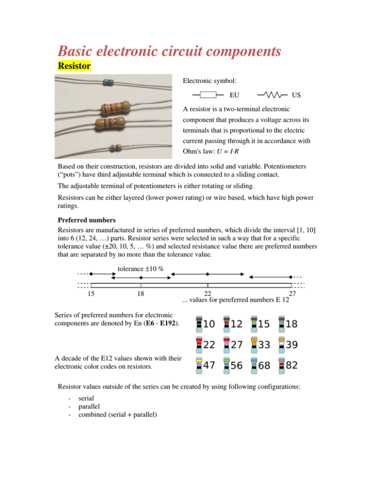
Basic electronic circuit components Resistor Electronic symbol: EU US A resistor is a two-terminal electronic component that produces a voltage across its terminals that is proportional to the electric current passing through it in accordance with Ohm's law: U = I·R Based on their construction, resistors are divided into solid and variable. Potentiometers (“pots”) have third adjustable terminal which is connected to a sliding contact. The adjustable terminal of potentiometers is either rotating or sliding. Resistors can be either layered (lower power rating) or wire based, which have high power ratings. Preferred numbers Resistors are manufactured in series of preferred numbers, which divide the interval [1, 10] into 6 (12, 24, …) parts. Resistor series were selected in such a way that for a specific tolerance value (±20, 10, 5, … %) and selected resistance value there are preferred numbers that are separated by no more than the tolerance value. tolerance ±10 % 15 18 22 27 ... values for pereferred numbers E 12 ... Series of preferred numbers for electronic components are denoted by En (E6 - E192). A decade of the E12 values shown with their electronic color codes on resistors. Resistor values outside of the series can be created by using following configurations: - serial parallel combined (serial + parallel) Serial configuration Resistors in series are connected in such a way that the end of the first resistor is connected to the beginning of the second and so on. In serial configuration, the total resistance equals to the sum of all the individual resistor values (for n resistors): R = R1 + R2 + R3 + ... + Rn Parallel configuration Resistors in parallel configuration are connected in such a way that the left endpoints of all resistors are connected at one terminal, and the right endpoints to another terminal. In this configuration the total resistance of n resistors equals to: 1 1 1 1 = + + ... + R R1 R2 Rn Electrical resistance Electrical resistance is a physical property, which measures the material’s opposition to the flow of a steady electric current. The Ohm’s Law states that current passing through a conductor is directly proportional to the potential difference or voltage across the conductor. Electrical resistance is the constant in this relationship. U = k × I, where k = R. Capacitor Electronic symbol: A capacitor is a two terminal electronic component; its dominant property is electrical capacitance. A capacitor is constructed from two electrodes and dielectric material. The type of dielectric material used to differentiate between capacitors types. Capacitor types The simplest capacitor consists of two parallel conductors which are separated by an insulating material (air, paper, mica, ...). The capacitance of a capacitor is increased when the areas of the parallel conductors are increased, the distance between conductors is decreased and permittivity of the environment is increased. Capacitors are manufactured (just like resistors) in series of preferred numbers in the range of picofarads to hundreds of nanofarads. Higher values (such as microfarads and milifarads) are electrolytic. Electrolytic capacitors have two aluminum foils (electrodes) with an absorbing material (paper) injected with an electrolyte placed in between them. The electrodes with the paper are rolled up and placed inside an aluminum cylindrical casing with two terminals (one terminal is connected directly to the case). Capacitors are used for - to separate direct current component from alternate one, circuit tuning (resonating circuits), filtering of supply voltage, elimination of interference from high frequencies construction of timing circuits, and so on. Capacitor values outside of the series can be created using following configurations: - serial parallel combined (serial + parallel) Serial configuration C C1 C2 C3 Cn Capacitors in series are connected in such a way that the terminal of the first capacitor is connected to the terminal of the second and so on. In serial configuration, the total capacitance equals to the inverse sum of all the individual capacitors values (for n capacitors): 1 1 1 1 = + + ... + C C1 C2 Cn Parallel configuration C C1 C2 C3 Cn Capacitors in parallel configuration are connected in such a way that the left endpoints of all capacitors are connected at one terminal, and the right endpoints to another terminal (when working with electrolytic capacitors, it is important to note the terminals polarity). In this configuration the total capacitance of n capacitors equals to the arithmetic sum of all individual capacitor values: C = C1 + C2 + C3 + ... + Cn Variable capacitors The capacitance can be adjusted with a rotating terminal. Variable capacitors are constructed from two or multiple electrodes that are arranged in semicircle and are rotated using one of the terminals. By rotating one of the terminals, the distance between the electrodes and the amount of surface area over lapping is varied and thus the capacitance changes. Variable capacitors are often used in L/C circuits to set the resonance frequency, e.g. to tune a radio. Electronic symbol: Inductor Electronic symbol: A coil is a passive electronic component representing inductance in the electrical circuit. A coil is formed by wounding an insulated solid wire around a frame. The basic unit of measurement is inductance (measured in Henries) which depends on the size of the coil, the number of wire turns and the permeability of core. The permeability is a measure of the degree of magnetization of the environment (material) resulting from the magnetic field. An increase in the inductance of the coil is achieved by inserting an iron core (ferrite) into the coil. A coil is made of an insulated conductor that is wound around a frame in one or more layers. The conductor in a coil should have as low resistance to minimize the temperature losses. For this reason copper is the most commonly used material. The wire turns have to be insulated from each other and thus a coating of lacquer is applied to the wires. There are three main uses of a coil in electrical engineering: For creating of a magnetic field from an electric current; the magnetic field is used to move or spin the core. Examples are the solenoids or the electric motors. For creating of an electric current from a magnetic field by induction; the coil is used as an inductor (carrier of inductance). The inductance property is used in LC circuits, radio-communications, etc. For converting of voltage in transformers. Inductance creates a magnetic field in the primary coil that generates an electrical current in the secondary coil in a transformer. The ratio of voltage is directly proportional to the number of turns in the coil. NETWORK A network is made up of resistances, inductances and capacitances connected together in some manner. A passive network is a network containing no source of energy; an active network is a network containing one or more sources of energy. VOCABULARY accordance – zhoda, súlad adjustable – nastaviteľný, regulovateľný core – jadro coil – cievka network – prenosový článok, sieť, reťazec manner – spôsob variable – premenlivý layered – vrstvené denote – naznačovať, ukazovať preferred – prednostné configuration – konfigurácia, zostava frame – rám, rámec, obrazec insert – vložiť solenoid – solenoid steady – stabilný hinder – brániť polarity – polarita sliding – kĺzanie sliding contact – posuvný kontakt terminal – svorka (prístroja, obvodu) two-terminal network – dvojpól two-port – dvojbrán, štvorpól dielectric – dielektrický permittivity – permitivita permeability – permeabilita electrolytic – elektrolytický foil – fólia inject – vložiť, vstreknúť interference – rušenie filtering – filtrovanie, filtrácia supply – zásobovanie, zdroj resonance – rezonancia, rezonovanie, chvenie wound – rana spin – točiť


