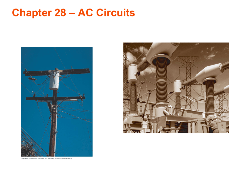
Chapter 28 – AC Circuits
advertisement

Chapter 28 – AC Circuits LC Circuit • Suppose switch closed at t = 0 with capacitor initially charged to Q. What is q(t)? � � dI � = −L � · dl ∆Vi = −Vc E =− dt -q i q dq VC = +q I=− C dt I d2 q q like harmonic L 2 + = 0 Looks oscillator! dt C d2 x m 2 + kx = 0 (mass on spring) dt q(t) = Q cos(ωt) ω = � 1 LC (resonant frequency) • Initially, energy is stored by capacitor in the form of an electric field. 1 1 Q2 2 U = CV = 2 2 C • When capacitor is drained (q=0), what form is the �energy? 1 • Notice that when q=0, |I| = Imax = Qω = Q LC 2 1Q 1 2 U= = LImax 2 C 2 All energy in inductor! • What form is energy in inductor? 1 2 LI = uB × volume 2 2 B • Magnetic energy density: uB = 2µ0 • Magnetic! for solenoid: • Always true (general result is based on a much more formal derivation) • Energy in an LC circuit oscillates between electric and magnetic • similar to mechanical harmonic oscillator (kinetic and potential) Damped LC oscillations • With resistance in the circuit, LC oscillations damp out. I -q I � +q dI � E · d� = VC + IR = −L dt dq I= dt d2 q dq 1 L 2 +R + q =0 dt C • underdamped case: dt q(t) = q0 exp(−R/(2L)t) cos �� 1 R2 − t LC 4L2 � • Similar to a damped mass on spring Driven AC Circuits • Driven resistor: Vemf (t) − IR = 0 Vemf I= R • Current in phase with driving voltage source. Driven Capacitor Vemf − VC = 0 I q Vc = = Vp sin ωt C dq I= = CVp ω cos ωt = Vp (Cω) sin(ωt + π/2) dt Imax Vp = XC 1 =⇒ XC = ωC Capacitive reactance + - • A light bulb is attached in series to a capacitor and an AC voltage source with an adjustable frequency. Keeping the peak voltage constant, the light bulb will be brightest for 1. 2. 3. 4. low frequencies high frequencies same for all frequencies Bulb doesn’t shine for any frequency ξ = Vp sin(ωt) 3 Driven RC Circuit (t) q ξ(t) − IR − =0 C R dq q R+ = Vp sin(ωt) dt C C dq Vp I= =� cos(ωt + δ) dt 1 2 δ = tan−1 (−ωRC) ( ωC ) + R2 Driven Inductor • Faraday’s Law of induction dI −Vp sin(ωt) = −L dt Vp I= L � sin(ωt) dt Vp I(t) = − cos(ωt) ωL Imax Vp = XL XL = ωL Inductive reactance � dI � = −L � · dl E dt Driven LR Circuit dI −V (t) + IR = −L dt if V (t) = V0 cos(ωt) V0 I(t) = � cos(ωt − φ) R2 + (Lω)2 φ = tan −1 wL R Jumping ring demo • why does ring always repel from solenoid (with AC circuit)? http://www.youtube.com/watch?v=Pl7KyVIJ1iE Jumping Ring Analysis I(t) • Suppose current in coils goes as I(t) = I0 sin(ωt) • The emf in loop will go as Vemf ∝ −dI/dt ∝ − cos(ωt) • The induced current will therefore go as Iring ∝ − cos(ωt − φ) φ = tan −1 wL R • Repulsive force when Iring and I are in opposite directions Jumping Ring Cont’d • If there were no phase difference between induced current and emf, induced current would be in same direction as I(t) half the time, and the ring would not jump! I(t) Vemf Jumping Ring Cont’d • Now add phase shift between induced emf and induced curent, given by −1 wL φ = tan R • For large inductance/and or high frequencies, phase shift is near 90°. Here is a phase shift of 70°: Vemf Now currents are in opposite directions more often than in same direction! I(t) Iind speaker crossover Driven LRC Circuit • An RLC circuit driven by an AC voltage source exhibits frequencydependent behavior. V (t) = Vp sin(ωd t) -q +q q dI −V (t) + IR + = −L C dt dq I= dt d2 q dq q L 2 +R + = Vp sin(ωd t) dt dt C Ip = � Vp R2 + (ωL − Vp 1 2 ωC ) Vp Ip = � = 2 2 Z R + (XL − XC ) I(t) = Ip sin(ωd t − φ) XL − XC tan φ = R Amplitude and phase in the driven RLC circuit • Peak current has a maximum at resonance: • resonant frequency ω =1 LC . (XL = XC = • Ip = Vp/Z � • At resonance, voltage and current are in phase L ) C Transformers and power supplies • A transformer is a pair of coils linked by mutual inductance. • An AC current in the primary induces a current in the secondary. • The secondary voltage differs from the primary voltage by the ratio of the number of turns. • Both step-up and step-down transformers are possible. dΦB ξ1 = −N1 (ΦB is flux per winding) dt dΦB ξ2 = −N2 dt ξ2 N2 V2 = = ξ1 N1 V1 |V1 |max = |ξ1 |max |V2 |max N2 = |V1 |max N1 Question 34.18 Transformers I 1) 30 V What is the voltage 2) 60 V 3) 120 V across the 4) 240 V lightbulb? 5) 480 V 120 V Question 34.20 Transformers III A 6 V battery is connected to one 1) greater than 6 V side of a transformer. The output 2) 6 V voltage across coil B is: 3) less than 6 V 4) zero A 6V B • Transformers are used to produce low voltages for electronic equipment. • Then they’re combined with diodes that convert AC to DC and capacitors to smooth the DC voltage. Input Power Vs Output Power • How does the input power compare to the output power? P1 = P2 • Ignoring self inductance, V1 N1 I2 = I1 = I1 V2 N2 P1 = V 1 I 1 Clicker Question If the resistance R is decreased what happens to I1? a) Increases b) Decreases c) Remains the same Transmission of Electrical Power • Electric power is most efficiently transmitted at high voltages. • This reduces I2R energy losses in the power lines. • But most end uses require lower voltages. • Transformers accomplish voltage changes throughout the power grid. Slide 26-11 Two-Phase Power to Your Home center tap is connected to ground rms = root mean squared: Slide 26-12


