5. Wheatstone Bridge
advertisement

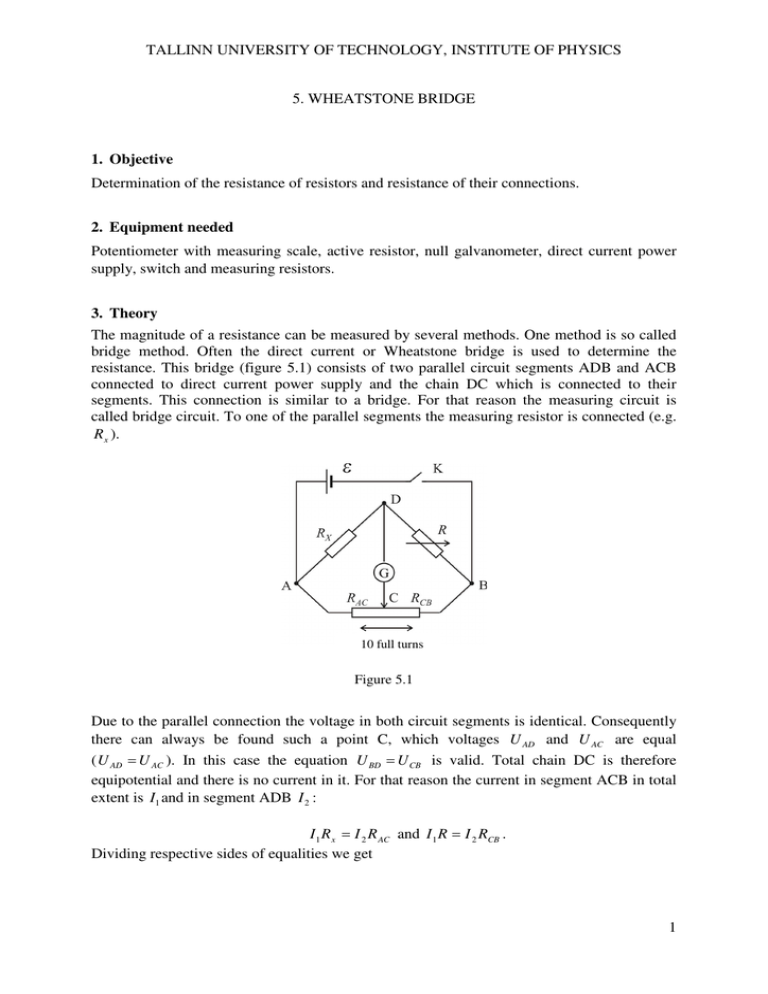
TALLINN UNIVERSITY OF TECHNOLOGY, INSTITUTE OF PHYSICS 5. WHEATSTONE BRIDGE 1. Objective Determination of the resistance of resistors and resistance of their connections. 2. Equipment needed Potentiometer with measuring scale, active resistor, null galvanometer, direct current power supply, switch and measuring resistors. 3. Theory The magnitude of a resistance can be measured by several methods. One method is so called bridge method. Often the direct current or Wheatstone bridge is used to determine the resistance. This bridge (figure 5.1) consists of two parallel circuit segments ADB and ACB connected to direct current power supply and the chain DC which is connected to their segments. This connection is similar to a bridge. For that reason the measuring circuit is called bridge circuit. To one of the parallel segments the measuring resistor is connected (e.g. R x ). 10 full turns Figure 5.1 Due to the parallel connection the voltage in both circuit segments is identical. Consequently there can always be found such a point C, which voltages U AD and U AC are equal ( U AD = U AC ). In this case the equation U BD = U CB is valid. Total chain DC is therefore equipotential and there is no current in it. For that reason the current in segment ACB in total extent is I1 and in segment ADB I 2 : I 1 R x = I 2 R AC and I 1 R = I 2 RCB . Dividing respective sides of equalities we get 1 TALLINN UNIVERSITY OF TECHNOLOGY, INSTITUTE OF PHYSICS Rx = R AC ⋅R. RCB (1) Hence, calculating Rx we have to know the value of resistance R and the ratio of RAC and RCB . As circuit segment ACB the calibrated potentiometer with the scale latitude of 10.00 units is used. Along the wire of potentiometer the sliding contact C divides the total resistance RACB of the segment into two parts (shoulders) in reference to all the same. Due to the homogeneous surface area the resistances of the part of wire is equal to respective length of l1 and l2 . Hence, the ratio of resistances in equation (1) can be replaced by respective ratio of length Rx = l1 ⋅R . l2 (2) Remember that relationship (2) is valid on condition that there is no current in chain DC. To obtain this situation in practical measurements the null galvanometer is switched on to the chain DC. If D and C potentials are different, a current passes through the galvanometer. To achieve the zero reading on the galvanometer one has to change whether point D potential by changing resistance R or point C potential by shifting the sliding contact along the wire of potentiometer. The bridge is balanced if no current flows through the galvanometer. Let’s find, in what position of the sliding contact the relative uncertainty is minimal. If the total length of the galvanometers wire is l, then l2 = l − l1 . Equation (2) acquires the shape Rx = R l1 , l − l1 the relative uncertainty of the searchable resistance appears 2 l1 ∆ 2 ∆Rx ∆R l − l1 = + . l1 Rx R l − l1 After modifying the following expression is obtained: ∆Rx = Rx (∆R )2 ⋅ l12 (l − l1 )2 + R 2 ((l ⋅ ∆l1 )2 + (l1∆l )2 ) . R ⋅ l1 (l − l1 ) Relative uncertainty is minimal, when denominator of the expression cited above is maximal. Let’s find the maximum condition for the function f (l1 ) = R ⋅ l1 (l − l1 ) : 2 TALLINN UNIVERSITY OF TECHNOLOGY, INSTITUTE OF PHYSICS df (l1 ) = R ⋅ l − 2 R ⋅ l1 = R(l − 2l1 ) = 0 , dl1 1 hence l1 = l . 2 The uncertainty of the measured resistance is minimal when in case of balanced bridge the sliding contact lies in the middle of the potentiometers scale ( l1 = l2 ). According to the formula (2) Rx = R . 4. Experimental procedure 1. Record the data of measuring devices. 2. Set up the circuit as shown at the work place, where R is active resistor, Rx measured resistor, and potentiometer used in segment ACB. 3. Compare the circuit to figure 5.2. 4. Ask for instructor to control the scheme and to give the task. 5. Put the sliding contact C in the middle of the potentiometers scale (reading 5,00). Changing resistance of active resistor until the galvanometer shows no deflection. Record the readings of potentiometer and resistance of the active resistor (respectively l1 and R). The switch can only be closed for short-term because for long-term it harms the galvanometer if the bridge is not in balance. 6. Balance the bridge at five different values of resistance of the active resistor by moving the sliding contact. In case of every balance position record l1 and R in the data table 5.1. Take into account that the readings of the resistor do not differ more than 10 % from these found in point 4. 7. Analogically measure other resistor and record measuring results in the similar data table 5.2. 8. Set up a connection of resistors based on the task given by your instructor and measure the resistance according to point 4 and 5. Record the results in the data table 5.3 (similar to the table 5.1), which subtitle must characterize studied connection of resistors. Table 5.1 Resistor number … measuring resistance. Nr l1 l2 R Rx R x − Rx (R − Rx ) 2 x 1. ... 5. 9. Ask the instructor to check measuring data and thereafter disconnect the circuit. 10. Compute the value of Rx for each case by the formula (2), find the average value Rx and its extended uncertainty U A ( Rx ) . Operate this procedure for each studied resistor and their connections. 3 TALLINN UNIVERSITY OF TECHNOLOGY, INSTITUTE OF PHYSICS 11. Compute the value of resistance of a group of resistances connected in series or in parallel issued from previously determined individual values and the theoretical formula. 12. Compute the combined uncertainty of the resistance found in point 10. Compare the value of resistance found in point 11 to the value found in point 10. 5. Questions and tasks 1. 2. 3. 4. 5. Formulate Kirchhoff’s rules for circuit. Explain the working principle of Wheatstone bridge. Derive the balanced condition of Wheatstone bridge. Why it is enough to know only the length of the potentiometers wire in this work? How is expressed the resistance of a conductor by its length, cross-sectional area and resistivity? Ω ⋅ mm 2 6. Define the units of resistance and resistivity Ω , Ωm , , m 7. Give the formulas to determine the total resistance of resistors connected in series or in parallel and give a reason for this. 8. Why the highest accuracy of measuring result is obtained when the sliding contact lies in the middle of potentiometer? 9. Why the galvanometer should not be switched on for a long time? 10. Three power supplies and three resistors are connected according to the figure 5.2. ε1 = 2,5V , ε 2 = 2,0V , ε 3 = 1,5V , R1 = 2,0Ω , R2 = 3,0Ω , R3 = 0,8Ω . Find current in the resistors. Do not count the interior resistances of the elements. Figure 5.2 11. Two pieces of iron wire have identical mass, but one is ten times bigger. Which one has the greater resistance and how much? 6. Literature 1. Halliday, D., Resnick, R., Walker, J. Fundamentals of Physics – 6th ed., USA, John Wiley&Sons, Inc., 2001. § 28-3, §28-7 4


