Chapter 24 Alternating
advertisement

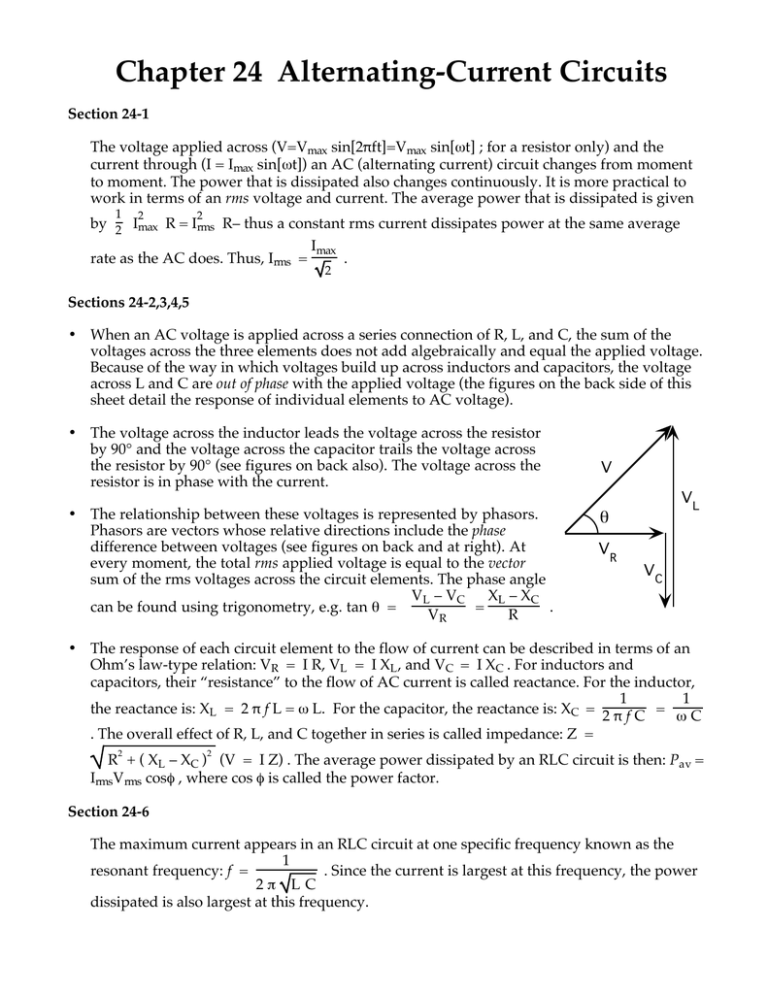
Chapter 24 Alternating-Current Circuits Section 24-1 The voltage applied across (V=Vmax sin[2πft]=Vmax sin[ωt] ; for a resistor only) and the current through (I = Imax sin[ωt]) an AC (alternating current) circuit changes from moment to moment. The power that is dissipated also changes continuously. It is more practical to work in terms of an rms voltage and current. The average power that is dissipated is given 1 2 2 by 2 Imax R = Irms R– thus a constant rms current dissipates power at the same average Imax rate as the AC does. Thus, Irms = . 2 Sections 24-2,3,4,5 • When an AC voltage is applied across a series connection of R, L, and C, the sum of the voltages across the three elements does not add algebraically and equal the applied voltage. Because of the way in which voltages build up across inductors and capacitors, the voltage across L and C are out of phase with the applied voltage (the figures on the back side of this sheet detail the response of individual elements to AC voltage). • The voltage across the inductor leads the voltage across the resistor by 90° and the voltage across the capacitor trails the voltage across the resistor by 90° (see figures on back also). The voltage across the resistor is in phase with the current. • The relationship between these voltages is represented by phasors. Phasors are vectors whose relative directions include the phase difference between voltages (see figures on back and at right). At every moment, the total rms applied voltage is equal to the vector sum of the rms voltages across the circuit elements. The phase angle VL – VC XL – XC can be found using trigonometry, e.g. tan θ = = . VR R V VL θ VR VC • The response of each circuit element to the flow of current can be described in terms of an Ohm’s law-type relation: VR = I R, VL = I XL , and VC = I XC . For inductors and capacitors, their “resistance” to the flow of AC current is called reactance. For the inductor, 1 1 the reactance is: XL = 2 π f L = ω L. For the capacitor, the reactance is: XC = 2 π f C = ω C . The overall effect of R, L, and C together in series is called impedance: Z = 2 2 R + ( XL – XC ) (V = I Z) . The average power dissipated by an RLC circuit is then: Pav = IrmsVrms cosφ , where cos φ is called the power factor. Section 24-6 The maximum current appears in an RLC circuit at one specific frequency known as the 1 resonant frequency: f = . Since the current is largest at this frequency, the power 2 π L C dissipated is also largest at this frequency. R Average power dissipated: 2 Pav = I rms R R f Vmax I max Vrms = I rms R ωt = 2πft V = Vmaxsin (2 π f t) I = Imaxsin (2 π f t) L The current is in phase with the voltage VLmax Pav = 0 (for ideal inductor: R L = 0) XL ωt = 2πft XL = ω L f Vrms = I rms X L I max VL = VLmaxsin (2 π f t + π ) 2 = VLmaxcos (2 π f t) C Pav = 0 The current lags the voltage by 90° or the voltage leads the current by 90° VCmax I max XC = 1/( ω C ) XC Vrms = I rms X C ωt = 2πft f VC = VCmaxsin (2 π f t – π ) 2 = –VCmaxcos (2 π f t) The current leads the voltage by 90° or the voltage lags the current by 90°


