Installation Guidelines
advertisement

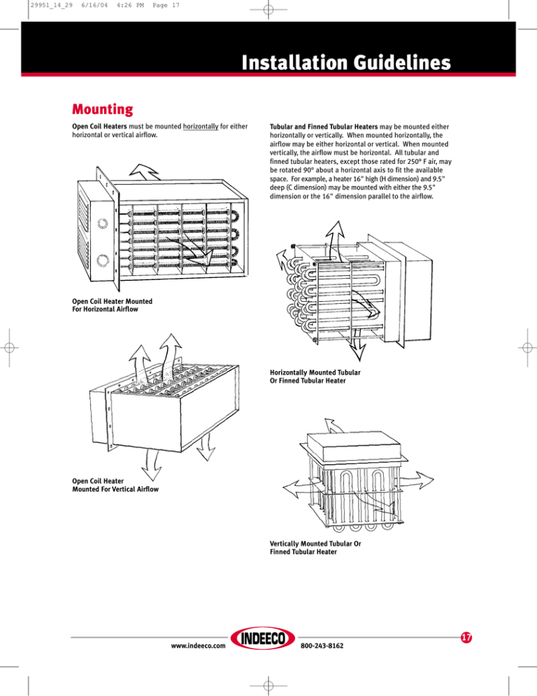
29951_14_29 6/16/04 4:26 PM Page 17 Installation Guidelines Mounting Open Coil Heaters must be mounted horizontally for either horizontal or vertical airflow. Tubular and Finned Tubular Heaters may be mounted either horizontally or vertically. When mounted horizontally, the airflow may be either horizontal or vertical. When mounted vertically, the airflow must be horizontal. All tubular and finned tubular heaters, except those rated for 250° F air, may be rotated 90° about a horizontal axis to fit the available space. For example, a heater 16" high (H dimension) and 9.5" deep (C dimension) may be mounted with either the 9.5" dimension or the 16" dimension parallel to the airflow. Open Coil Heater Mounted For Horizontal Airflow Horizontally Mounted Tubular Or Finned Tubular Heater Open Coil Heater Mounted For Vertical Airflow Vertically Mounted Tubular Or Finned Tubular Heater 17 www.indeeco.com 800-243-8162 29951_14_29 6/16/04 4:26 PM Page 18 Installation Guidelines Support Low Temperature Heaters, suitable for 250° F maximum outlet air, are attached to the ductwork or oven wall with sheet metal screws through the base of the terminal box, as shown. Higher Temperature Heaters, those rated for 400° F air and higher, must be bolted to the duct or oven wall using the bolt holes provided in the steel flange at the base of the terminal box. Weld nuts or captive nuts may be provided in the wall or a mating flange can be provided in the field. Installation Of 250° F Heater Installation Of Heater Rated For 400° F And Higher All Horizontally Mounted Heaters, except those weighing less than 25 lbs., should be supported inside the oven or duct with rails or hangers. Heaters mounted vertically through the top of the oven or duct need not be supported internally. However, the structure should be adequate to carry the entire heater weight. Insulation If the heater is mounted through an opening in an insulated wall, special precautions must be taken to insure that the entire heated length is in the airstream. Otherwise, the elements shadowed by the insulation will overheat and burn out. Open Coil heaters designed for 1200° F air are provided with 4" of insulation under the mounting plate. If the insulated oven wall is thicker than 4", additional insulation should be provided in the heater. Heaters rated for lower outlet air temperatures may also be provided with insulation under the mounting plate or with extended terminal cold sections to clear the oven wall. The standard open coil construction will clear up to 2" of insulation without modification. 18 www.indeeco.com Finned Tubular heaters may also be provided with insulation under the mounting plate or extended cold sections. Heaters will clear 2" of insulation without modification. Tubular heaters rated for 1200° F outlet air are provided with 4" of insulation under the mounting flange, which should be extended for heavier oven walls. Heaters rated for 750° F outlet air may also be provided with 4" of insulation under the mounting plate, or may safely be installed through a wall up to 2" thick without modification. 800-243-8162 29951_14_29 6/16/04 4:26 PM Page 19 Installation Guidelines Overtemperature Protection Field Wiring To prevent overheating under adverse conditions, overtemperature protection is recommended. Four types of protective devices are available: All heaters in the listings are designed for 480 volts, three phase. Therefore, three power leads must be brought into the heater for each circuit through the knockouts provided in the terminal box. The number of circuits is shown in the listings. The current drawn by each circuit is calculated as follows: Thermal Cutout – A thermostat, set approximately 50° higher than normal operating temperature, can be built into heaters rated for 250° F maximum outlet air. The built-in thermostat or built-in combination thermostat/thermal cutout can be used for this purpose. For higher temperature heaters, a remote thermostat may be used as a thermal cutout. Built-in Thermocouple – A thermocouple, sensing sheath or air temperature, can be wired to a remotely mounted thermocouple controller, set approximately 50° F above normal operating temperature. The controller then acts as a thermal cutout. Line Current = Circuit KW x 1000 Voltage x 1.73 All wiring should be per the National Electrical Code and any special provisions in local codes. Wiring insulation must be suitable for the terminal box ambient temperature as determined from Chart F. Note that lower temperature wiring insulation may be used on heaters with insulation under the mounting flange. Built-in Airflow Switch – A differential pressure type airflow switch may be built into 150° F heaters. By sensing the difference in pressure between the process air and the outside atmosphere, it will shut down the heater when there is a sudden drop in process pressure. Fan Interlock Relay – A relay interlocking the fan motor with the heater control circuit will shut down the heater if there is no power to the fan. Note, however, that this device does not protect against a stalled motor nor against a blockage in the airstream that would result in little or no airflow, even though the fan is running. Chart F Terminal Box Temperature 19 www.indeeco.com 800-243-8162 29951_14_29 6/16/04 4:26 PM Page 20 Installation Guidelines Airflow Uniformity To prevent hot spots, airflow must be uniformly distributed across the heater face. These drawings illustrate typical heater misapplications which result in nonuniform airflow. If one or more of these conditions cannot be avoided, consult INDEECO for assistance. In most cases we can provide a pressure plate or nonheated zones in the heater to overcome these problems. 20 Heater Too Close To Elbow Heater Adjacent To Transition Heater Too Close To Fan Heater Partially Blocked By Filter Or Frame Member www.indeeco.com 800-243-8162


