Electrical Transformers - University of Washington
advertisement

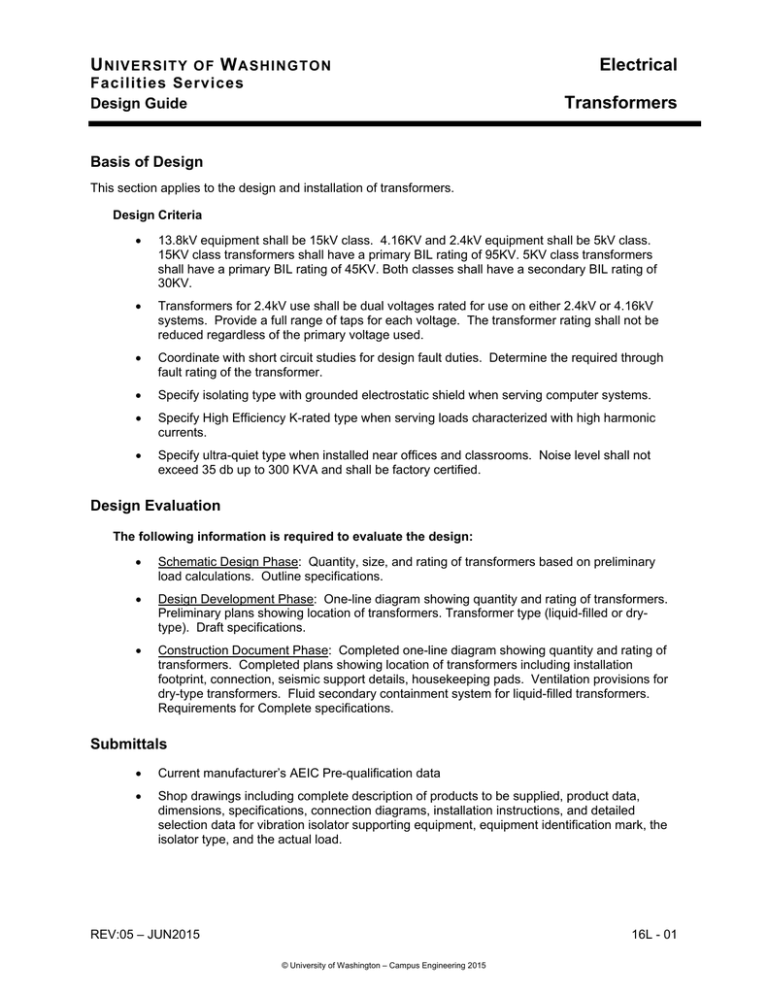
U NIVERSITY OF W ASHINGTON Facilities Services Design Guide Electrical Transformers Basis of Design This section applies to the design and installation of transformers. Design Criteria 13.8kV equipment shall be 15kV class. 4.16KV and 2.4kV equipment shall be 5kV class. 15KV class transformers shall have a primary BIL rating of 95KV. 5KV class transformers shall have a primary BIL rating of 45KV. Both classes shall have a secondary BIL rating of 30KV. Transformers for 2.4kV use shall be dual voltages rated for use on either 2.4kV or 4.16kV systems. Provide a full range of taps for each voltage. The transformer rating shall not be reduced regardless of the primary voltage used. Coordinate with short circuit studies for design fault duties. Determine the required through fault rating of the transformer. Specify isolating type with grounded electrostatic shield when serving computer systems. Specify High Efficiency K-rated type when serving loads characterized with high harmonic currents. Specify ultra-quiet type when installed near offices and classrooms. Noise level shall not exceed 35 db up to 300 KVA and shall be factory certified. Design Evaluation The following information is required to evaluate the design: Schematic Design Phase: Quantity, size, and rating of transformers based on preliminary load calculations. Outline specifications. Design Development Phase: One-line diagram showing quantity and rating of transformers. Preliminary plans showing location of transformers. Transformer type (liquid-filled or drytype). Draft specifications. Construction Document Phase: Completed one-line diagram showing quantity and rating of transformers. Completed plans showing location of transformers including installation footprint, connection, seismic support details, housekeeping pads. Ventilation provisions for dry-type transformers. Fluid secondary containment system for liquid-filled transformers. Requirements for Complete specifications. Submittals Current manufacturer’s AEIC Pre-qualification data Shop drawings including complete description of products to be supplied, product data, dimensions, specifications, connection diagrams, installation instructions, and detailed selection data for vibration isolator supporting equipment, equipment identification mark, the isolator type, and the actual load. REV:05 – JUN2015 16L - 01 © University of Washington – Campus Engineering 2015 U NIVERSITY OF W ASHINGTON Facilities Services Design Guide Electrical Transformers Products, Material and Equipment Approved Manufacturers 1) ABB 2) Square D 3) GE 4) Siemens Unless otherwise specified, transformers shall meet the sound levels of NEMA, ANSI and/or IEEE, whichever is most conservative. Supply certified tests on request of the Owner. Note: This may require that architectural solutions be used. Dry-Type Transformers The transformer shall be of fire-resistant, air insulated, dry type construction, cooled by the circulation of air through the windings. Transformers shall be 150 degree C., class H, 220 degree insulation, indoor ventilated dry type, Vacuum Pressure Impregnated. The entire core and coil assembly shall be Vacuum Pressure Impregnated (VPI) with a high temperature thermo setting polyester varnish. The total VPI process shall apply a one (1) cycle shield of resin to the coils and bus, core and support structure. The VPI process shall effectively encapsulate the entire core and coil assembly which results in a transformer which is virtually impermeable to moisture, dust, dirt, salt air and other industrial contaminants. The electrical insulation system shall utilize Class H material in a fully rated 220 degree C. system. Base transformer design temperature rise on a 30 C average ambient over a 24 hour period with a maximum of 40 C. Solid insulation in the transformer shall consist of inorganic materials such as porcelain, glass fiber, electrical grade glass polyester on Nomex. All insulating materials must be rated for continuous 220 C duty. The insulation between the high and low voltage coils shall be more than sufficient for the voltage stress without the need of a varnish. Transformers shall be of the highest quality, manufactured by firm that has manufactured such apparatus for at least 25 years. Transformers will have high voltage (primary) terminal markings: 1) “H1" to "A" Phase 2) "H2" to "C" Phase 3) "H3" to "B" Phase 16L - 02 REV:05 – JUN2015 © University of Washington – Campus Engineering 2015 U NIVERSITY OF W ASHINGTON Facilities Services Design Guide Electrical Transformers Low voltage switchgear normally connected to building power service transformers will be constructed in accordance with industry standards and will have their buses identified "1", "2", "3", "N". Transformers will have low voltage (secondary) terminal markings "X1", "X2", "X3", "X0" from left to right or top to bottom when facing the low voltage terminals and the switchgear shall be as follows: 1) "X1" to "1" (BUS) 2) "X2" to "2" (BUS) 3) "X3" to "3" (BUS) It is to be noted that transformer connections as indicated above will result in a rotation sequence at the low voltage switchgear of "1", "2", "3". All transformers shall be provided with American Standard connection, 30 degree negative angular displacement. Transformer impedance should be about 5.75% (7% for three transformer networks). For two transformer networks, special transformer impedances must be determined so that voltage regulation issues are resolved. Confer with Campus Engineering for these applications. Enclosure ventilation openings shall be louvered or fine mesh screened. Straight punched holes are not acceptable for safety reasons. Transformers shall be provided with the following: 4) Diagrammatic nameplate listing all detailed information as required by NEMA Standards. 5) Four 2½ % full capacity taps, two above and two below rated voltage. 6) Lifting lugs 7) Base suitable for skidding in all directions. Transformer case shall be supplied in a knockdown design. 8) Windings shall be copper. 9) Equipped with a fully insulated secondary neutral bushing (externally groundable) to permit the use of a neutral conductor or current transformer or sensing ground fault currents. 10) Terminal markings shall be provided on the transformer terminals and shall clearly identify each terminal when doors or covers are opened. 11) Electrical connections between the transformer and the switchgear shall be provided by the switchgear manufacturer. 12) Air-filled primary terminal chamber adequately sized for stress cone termination of 3 or 6 single conductors, as indicated. 13) Service transformers serving the "normal" loads shall be provided with automatic temperature-controlled fans. These forced air (FA) units shall contain all necessary components and wiring, including fans, for increasing the KVA ratings by 33% at 150 degrees C. The (FA) package shall include an electronic temperature monitor and fan control unit with the following features: Digital readout, green - power on, yellow fan on, red - high temperature indicating lights; audible high temperature alarm with alarm silence push button; max. temperature memory with read and reset switch; auto/manual fan control switch; system test switch; temperature sensing in all three REV:05 – JUN2015 16L - 03 © University of Washington – Campus Engineering 2015 U NIVERSITY OF W ASHINGTON Facilities Services Design Guide Electrical Transformers low voltage coils. Auxiliary alarm contact and means for remote control and temperature monitoring shall be provided. Control power shall be provided from a control power transformer in the secondary switchgear. 14) Emergency Unit Substation transformers shall be pre-wired for future fan cooling, including RTD's or thermocouples imbedded in the windings for temperature control (same as FA package described above but without fans). 15) Provide continuous ¼" x 2" ground bus for connection to adjacent compartment's switchgear. The transformer shall be designed to meet the sound level standards for dry-type transformers as defined in NEMA TR1. The following factory tests shall be made on all transformers, although not necessarily in the order listed. All tests shall be in accordance with the latest revision of ANSI Test Code C57.12.91 and NEMA TR1, IEEE 262A-1974. 1) Resistance measurements of all windings on the rated voltage connection of each unit and at the tap extremes of one unit only of a given rating on this for indoor or outdoor installation 2) Ratio tests on the rated voltage connection and on all tap connections 3) Polarity and phase-relation tests on the rated voltage connections 4) No-load loss at rated voltage on the rated voltage connection 5) Exciting current at rated voltage on the rated voltage connection 6) Impedance and load loss at rated current on the rated voltage connection of each unit and on the tap extremes of one unit only of a given rating on this project 7) Temperature test(s) shall be made on one unit only of a project covering one or more units of a given KVA rating. Tests shall not be required when there is available a record of a temperature test on an essentially duplicate unit. When a transformer is supplied with auxiliary cooling equipment to provide more than one KVA rating, temperature tests as listed above shall be made on the lowest KVA AA rating [and the highest KVA FA rating]. 8) Applied potential test 9) Induced potential tests Steel panel enclosure with louvered openings to guard against insertion of foreign objects Ventilated dry type transformers shall comply with ANSI C57.12.51. 16L - 04 REV:05 – JUN2015 © University of Washington – Campus Engineering 2015 U NIVERSITY OF W ASHINGTON Facilities Services Design Guide Electrical Transformers Liquid Filled Transformers For outdoor use only Liquid-filled Pad Mount Transformers shall comply with ANSI C57.12.27 Dead front design only May be integral with primary switching, fusing and separable connection compartment Connections shall be via bushing wells for Elastimold or Colt Industries removable studs. Removable bushings shall be included. Load Break parking stands shall be included. Protection shall be via bayonet fuse. No isolation links are allowed. Liquid-filled transformers with a capacity of 55-gallons of insulating oil or greater shall have a secondary containment system. This is to prevent oil from discharging to the environment in case of accidental ruptures. The secondary system requirements shall be designed and included in the construction documents. Vibration Isolation MOUNTING TYPE - Unit DNP (Double Neoprene Pad): Neoprene pad isolators shall be formed by two layers of ¼-inch to 5/16-inch thick ribbed or waffled neoprene, separated by a stainless steel or aluminum plate. These layers shall be permanently adhered together. Neoprene shall be 40 to 50 durometer. The pads shall be sized so that they will be loaded within the manufacturer's recommended range. A steel top plate equal to the size of the pad shall be provided to transfer the weight of the supported unit to the pads. Acceptable manufacturers shall be: 1) Amber/Booth 2) Korfund Dynamics 3) Mason Industries 4) Peabody Noise Control 5) Vibration Mountings Control 6) Kinetics Noise Control Installation, Fabrication and Construction Units shall be anchored to their pads as required to meet seismic zone requirements. Initially connect at “normal tap”. After facility is completely energized, measure the primary and secondary voltages at all transformers and service switchboard. Forward a list to Engineer for evaluation. Reconnect and adjust taps as directed. All costs associated with this work are to be included in base bid. REV:05 – JUN2015 16L - 05 © University of Washington – Campus Engineering 2015 U NIVERSITY OF W ASHINGTON Facilities Services Design Guide Electrical Transformers Vibration Isolation Provide vibration control devices, materials and related items. Perform all work as specified in this section to provide complete vibration isolation systems in proper working order. Coordinate the size, location, and special requirements of vibration isolation equipment and systems with other trades. Coordinate plan dimensions with size of housekeeping pads. Size isolators to meet the specified loading requirements. Should equipment cause excessive noise or vibration, the Contractor shall be responsible for remedial work required reducing noise and vibration levels. “Excessive” is defined as exceeding the manufacturer's specifications for the unit in question. Upon completion of the work, the Owner's Representative shall inspect the installation and shall inform the installing contractor of any further work that must be completed. Make all adjustments as directed. This work shall be done before vibration isolation systems are accepted. END OF DESIGN GUIDE SECTION 16L - 06 REV:05 – JUN2015 © University of Washington – Campus Engineering 2015


