Modello Lineare a Tratti del Diodo Spiegato
advertisement
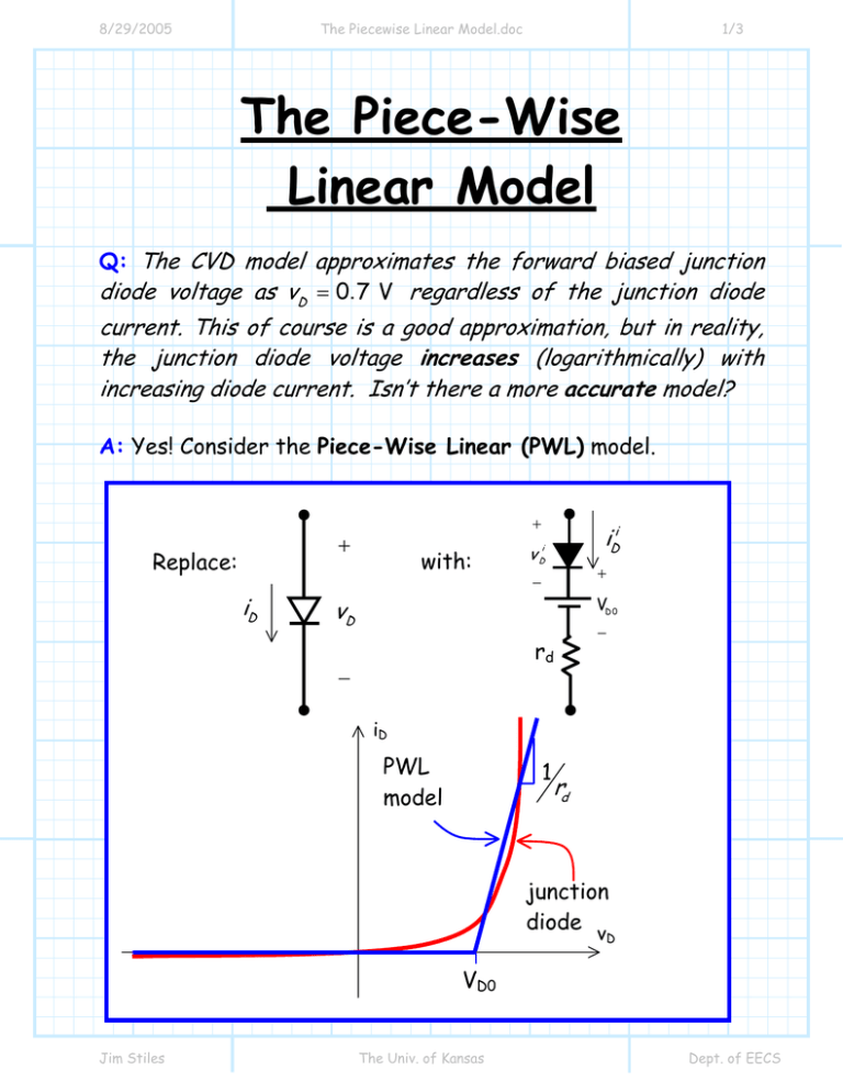
8/29/2005 The Piecewise Linear Model.doc 1/3 The Piece-Wise Linear Model Q: The CVD model approximates the forward biased junction diode voltage as vD = 0. 7 V regardless of the junction diode current. This of course is a good approximation, but in reality, the junction diode voltage increases (logarithmically) with increasing diode current. Isn’t there a more accurate model? A: Yes! Consider the Piece-Wise Linear (PWL) model. + + Replace: iD with: v iDi i D + − VD 0 vD rd − − iD PWL model 1 rd junction diode v D VD0 Jim Stiles The Univ. of Kansas Dept. of EECS 8/29/2005 The Piecewise Linear Model.doc 2/3 In other words, replace the junction diode with three devices— an ideal diode, in series with some voltage source (not 0.7 V!) and a resistor. To find approximate current and voltage values of a junction diode circuit, follow these steps: Step 1 - Replace each junction diode with the three devices of the PWL model. Note you now a have an IDEAL diode circuit! There are no junction diodes in the circuit, and therefore no junction diode knowledge need be (or should be) used to analyze it. Step 2 - Analyze the IDEAL diode circuit. Determine iDi and vDi for each IDEAL diode. IMPORTANT NOTE !!! PLEASE READ THIS CAREFULLY: Make sure you analyze the resulting circuit precisely as we did in section 3.1. You assume the same IDEAL diode modes, you enforce the same IDEAL diode values, and you check the same IDEAL diode results, precisely as before. Once we replace the junction diodes with the CVD model, we have an IDEAL diode circuit—no junction diodes are involved! Step 3 – Determine the approximate values iD and vD of the junction diode from the ideal diode values iDi and vDi : Jim Stiles The Univ. of Kansas Dept. of EECS 8/29/2005 The Piecewise Linear Model.doc + iD vD 3/3 + iD ≈ iDi vD ≈ v Di + VD 0 + iDi rd − v i D − rd iDi + VD 0 − Note therefore, if the IDEAL diode (note here I said IDEAL diode) is forward biased (iDi > 0 ), then the approximation of the junction diode current will likewise be positive ( iD > 0 ), and the approximation of the junction diode voltage (unlike the ideal diode voltage of vDi = 0 ) will be: vD = vDi + VD 0 + iDi rd = 0.0 + VD 0 + iDi rd = VD 0 + iDi rd However, if the IDEAL diode is reversed biased (iDi = 0 ), then the approximation of the junction diode current will likewise be zero (iD = 0 ), and the approximation of the junction diode voltage (unlike the ideal diode voltage of vDi < 0 ) will be: vD = vDi + VD 0 + iDi rd = vDi +VD 0 + 0 vD < VD 0 NOTE: Do not check the resulting junction diode approximations. You do not assume anything about the junction diode, so there is nothing to check regarding the junction diode answers. Jim Stiles The Univ. of Kansas Dept. of EECS
