The electrical system is shown in the diagram. The red wire is
advertisement

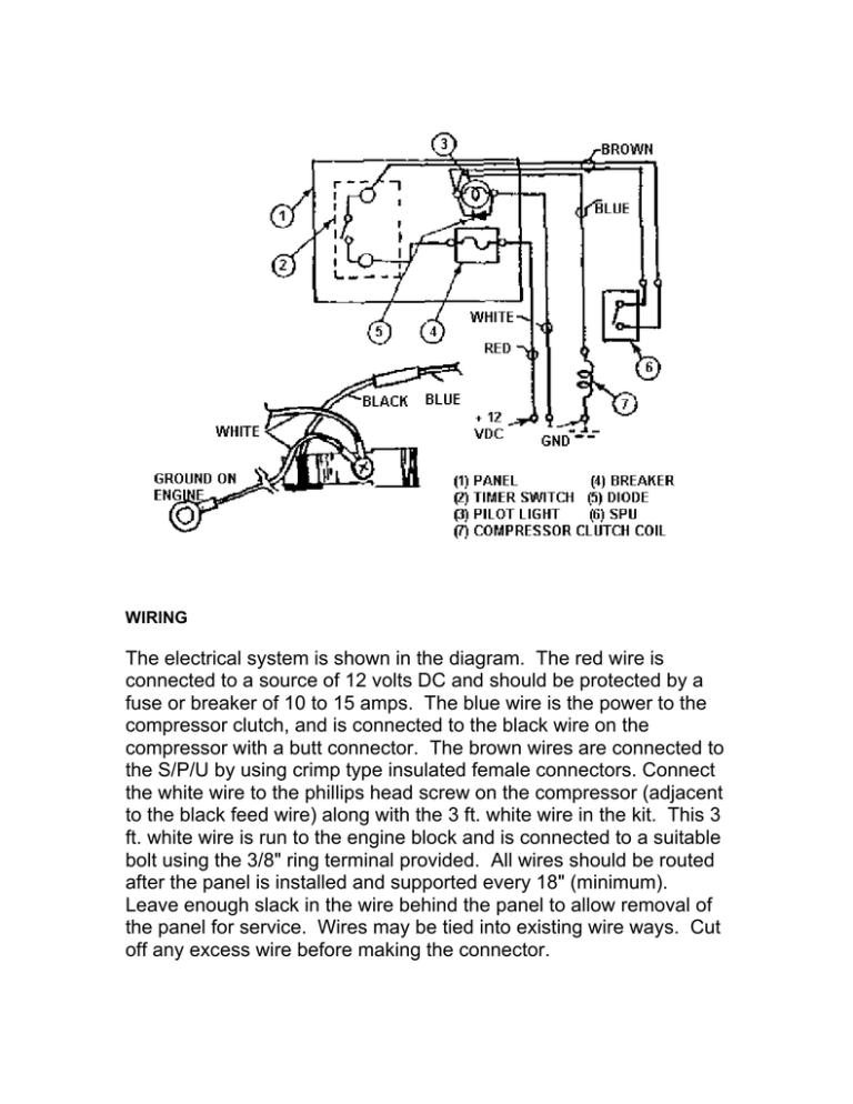
WIRING The electrical system is shown in the diagram. The red wire is connected to a source of 12 volts DC and should be protected by a fuse or breaker of 10 to 15 amps. The blue wire is the power to the compressor clutch, and is connected to the black wire on the compressor with a butt connector. The brown wires are connected to the S/P/U by using crimp type insulated female connectors. Connect the white wire to the phillips head screw on the compressor (adjacent to the black feed wire) along with the 3 ft. white wire in the kit. This 3 ft. white wire is run to the engine block and is connected to a suitable bolt using the 3/8" ring terminal provided. All wires should be routed after the panel is installed and supported every 18" (minimum). Leave enough slack in the wire behind the panel to allow removal of the panel for service. Wires may be tied into existing wire ways. Cut off any excess wire before making the connector.


