NEMA & IEC Terminal Markings Guide
advertisement
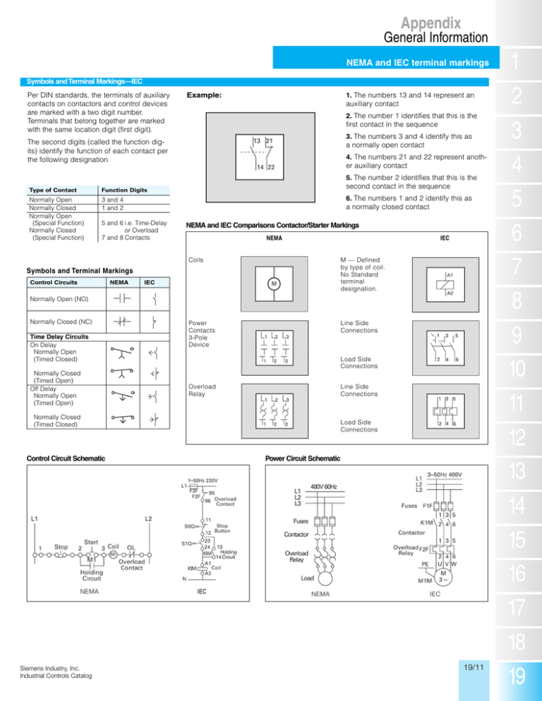
Appendix General Information NEMA and IEC terminal markings Symbols and Terminal Markings—IEC Per DIN standards, the terminals of auxiliary contacts on contactors and control devices are marked with a two digit number. Terminals that belong together are marked with the same location digit (first digit). 1. The numbers 13 and 14 represent an auxiliary contact Example: 2. The number 1 identifies that this is the first contact in the sequence 3. The numbers 3 and 4 identify this as a normally open contact The second digits (called the function digits) identify the function of each contact per the following designation. Type of Contact Function Digits Normally Open Normally Closed Normally Open (Special Function) Normally Closed (Special Function) 3 and 4 1 and 2 4. The numbers 21 and 22 represent anoth- er auxiliary contact 5. The number 2 identifies that this is the second contact in the sequence 6. The numbers 1 and 2 identify this as a normally closed contact 5 and 6 i.e. Time-Delay or Overload 7 and 8 Contacts NEMA and IEC Comparisons Contactor/Starter Markings NEMA IEC Coils M — Defined by type of coil. No Standard terminal designation. Power Contacts 3-Pole Device Line Side Connections Symbols and Terminal Markings Control Circuits NEMA IEC Normally Open (NO) Normally Closed (NC) Time Delay Circuits On Delay Normally Open (Timed Closed) Normally Closed (Timed Open) Off Delay Normally Open (Timed Open) Load Side Connections Overload Relay Line Side Connections Normally Closed (Timed Closed) Load Side Connections Power Circuit Schematic Control Circuit Schematic NEMA Siemens Industry, Inc. Industrial Controls Catalog IEC NEMA IEC 19/11
