DTC P1520/52 Stop Light Switch Signal Malfunction
advertisement
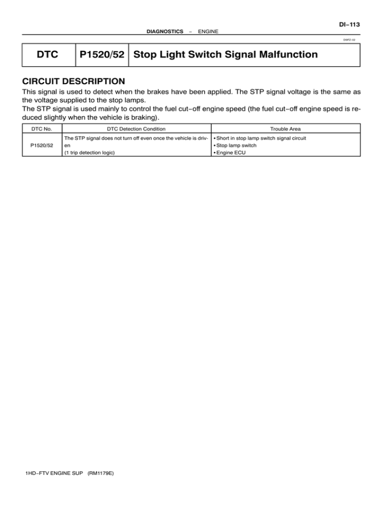
DI−113 DIAGNOSTICS − ENGINE DI9FZ−02 DTC P1520/52 Stop Light Switch Signal Malfunction CIRCUIT DESCRIPTION This signal is used to detect when the brakes have been applied. The STP signal voltage is the same as the voltage supplied to the stop lamps. The STP signal is used mainly to control the fuel cut−off engine speed (the fuel cut−off engine speed is reduced slightly when the vehicle is braking). DTC No. DTC Detection Condition P1520/52 The STP signal does not turn off even once the vehicle is driven (1 trip detection logic) 1HD−FTV ENGINE SUP (RM1179E) Trouble Area S Short in stop lamp switch signal circuit S Stop lamp switch S Engine ECU DI−114 − DIAGNOSTICS ENGINE WIRING DIAGRAM Engine ECU S6 Stop Lamp Switch J/B No. 4 B−R R−G 3 Cowl Side J/B LH 35 G−W 2D 1 4E 2 9 4E 4 J/B No. 4 15 13 4D 26 G−W 2E 35 2K 9 4C Cowl Side J/B RH*1 Cowl Side J/B LH*2 5 4 2M*1 3M*2 12 R−G E18 ST1− G−W 19 E18 STP 2M*1 3M*2 G−R Stop Lamp B−R Cowl Side J/B RH 8 3E 2D IGN 31 STOP 4 3E 2C 1 Cowl Side J/B LH 1 B−G J/B NO. 2 F38 Fusible Link Block ALT Ignition Switch Battery B Battery *1: RHD *2: LHD A23872 1HD−FTV ENGINE SUP (RM1179E) DI−115 DIAGNOSTICS − ENGINE INSPECTION PROCEDURE HINT: Read freeze frame data using the intelligent tester II. Freeze frame data records the engine conditions when a malfunction is detected. When troubleshooting, freeze frame data can help determine if the vehicle was running or stopped, if the engine was warmed up or not, and other data from the time the malfunction occurred. 1 Check operation of stop lamp. CHECK: Check if the stop lamps go on and off normally when the brake pedal is depressed and released. NG Check and repair stop lamp circuit. OK 2 Check STP signal. Brake Pedal Depressed When using intelligent tester II: PREPARATION: (a) Connect the intelligent tester II to the DLC3. (b) Turn the ignition switch ON and push the intelligent tester II main switch ON. CHECK: Read the STP signal on the intelligent tester II. OK: Brake Pedal Released STP A23889 1HD−FTV ENGINE SUP (RM1179E) STP Signal Depressed ON Released OFF When not using intelligent tester II: PREPARATION: Turn the ignition switch ON. CHECK: Check the voltage between terminal STP of the engine ECU connector and body ground. OK: OK NG Brake Pedal Brake Pedal Voltage Depressed 7.5 to 14 V Released Below 1.5 V Check for intermittent problems (See page DI−4). DI−116 DIAGNOSTICS 3 − ENGINE Check stop lamp switch (See Pub No. RM616E2, page BE−58) NG Replace or replace stop lamp switch. OK 4 Check harness and connector between engine ECU and stop lamp switch (See page IN−19). NG OK Check and replace engine ECU (See page IN−19). 1HD−FTV ENGINE SUP (RM1179E) Repair or replace harness or connector.
