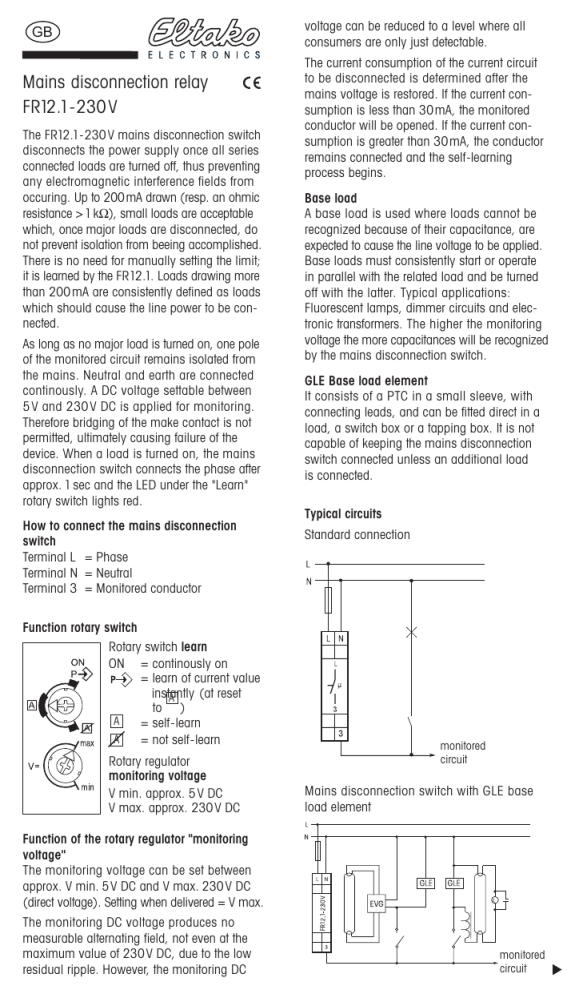
Mains disconnection relay FR12.1-230V

GB
Mains disconnection
relay
FR12.1-230 V
The FR12.1-230 V mains disconnection switch disconnects the power supply once all series connected loads are turned off, thus preventing any electromagnetic interference fields from occuring. Up to 200 mA drawn (resp. an ohmic resistance > 1 k Ω ), small loads are acceptable which, once major loads are disconnected, do not prevent isolation from beeing accomplished.
There is no need for manually setting the limit; it is learned by the FR12.1. Loads drawing more than 200 mA are consistently defined as loads which should cause the line power to be connected.
As long as no major load is turned on, one pole of the monitored circuit remains isolated from the mains. Neutral and earth are connected continously. A DC voltage settable between
5 V and 230 V DC is applied for monitoring.
Therefore bridging of the make contact is not permitted, ultimately causing failure of the device. When a load is turned on, the mains disconnection switch connects the phase after approx. 1 sec and the LED under the "Learn" rotary switch lights red.
How to connect the mains disconnection switch
Terminal L = Phase
Terminal N = Neutral
Terminal 3 = Monitored conductor
Function rotary switch
Rotary switch learn
ON = continously on
= learn of current value
A
A to )
= self-learn
= not self-learn
Rotary regulator monitoring voltage
V min. approx. 5 V DC
V max. approx. 230 V DC
Function of the rotary regulator "monitoring voltage"
The monitoring voltage can be set between approx. V min. 5 V DC and V max. 230 V DC
(direct voltage). Setting when delivered = V max.
The monitoring DC voltage produces no measurable alternating field, not even at the maximum value of 230 V DC, due to the low residual ripple. However, the monitoring DC voltage can be reduced to a level where all consumers are only just detectable.
The current consumption of the current circuit to be disconnected is determined after the mains voltage is restored. If the current consumption is less than 30 mA, the monitored conductor will be opened. If the current consumption is greater than 30 mA, the conductor remains connected and the self-learning process begins.
Base load
A base load is used where loads cannot be recognized because of their capacitance, are expected to cause the line voltage to be applied.
Base loads must consistently start or operate in parallel with the related load and be turned off with the latter. Typical applications:
Fluorescent lamps, dimmer circuits and electronic transformers. The higher the monitoring voltage the more capacitances will be recognized by the mains disconnection switch.
GLE Base load element
It consists of a PTC in a small sleeve, with connecting leads, and can be fitted direct in a load, a switch box or a tapping box. It is not capable of keeping the mains disconnection switch connected unless an additional load is connected.
Typical circuits
Standard connection monitored circuit
Mains disconnection switch with GLE base load element monitored circuit
Elder rotary dimmers with phase-fired control
(ON before zero crossing) for resistive and inductive loads
Can mostly be operated at V=max if no additional standby consumer is in the circuit.
Otherwise see "Modern rotary dimmers".
Rotary dimmer monitored circuit
L
N monitored circuit
Modern rotary dimmers and rotary dimmers with phase-fired control (OFF before zero crossing) for electronic transformers
Only dimmers with an additional terminal mains disconnection switch can be used.
L N A1 A2 max.
500 W
3
N
L
Rotary dimmer electronic transformer monitored circuit
Touch dimmers and sensor dimmers cannot be used. The universal dimmer switch EUD61NP and a push-button from the associated switch product range can replace a touch dimmer.
Remote control dimmers
We recommend as remote control dimmers the impulse dimmer switches ESD12UF. On these devices, terminal L is 'tapped' ahead of the mains disconnection relay, thus, maintainig the complete function. An integrated cut-off relay takes over the mains disconnection of the circuit. Mechanical push-buttons are connected to T1 and T2. Only a low DC voltage is impressed on the control wire.
If the application of the ESD12UF is not possible for reasons of installation the type EUD12NP can be used. Here the terminal L is connected after the mains disconnection relay.
As a result the memory fuction is switched off.
Switched-mode power supplies in consumer electronic units (e.g. TV sets) and plug-in power supply units
Only specific units or power supplies are detected and disconnected by the mains disconnection switch, even while in standby mode.
Where units or power supplies in a monitored circuit are not to be disconnected these must be isolated from line power by a switched socket outlet or a plug connector so that the function of the mains disconnection switch is not affected.
Timed shutter control directly on the window
Only specific shutter controls are detected and disconnected by the mains disconnection relay. If the shutter controls in the circuit to be disconnected should not be disabled, conventional shutter switches must be used instead.
Tube-mounted motors with electronic limit switches must be wired with a base load in parallel to the sense of rotation control, provided this is permitted by the manufacturer of the tube-mounted motor.
Warning !
Only a trained electrician may install this equipment, otherwise there is a risk of fire or electric shock.
01/2007 Specifications subject to change. 4938


