Problem 5.37 Obtain an expression for the self
advertisement
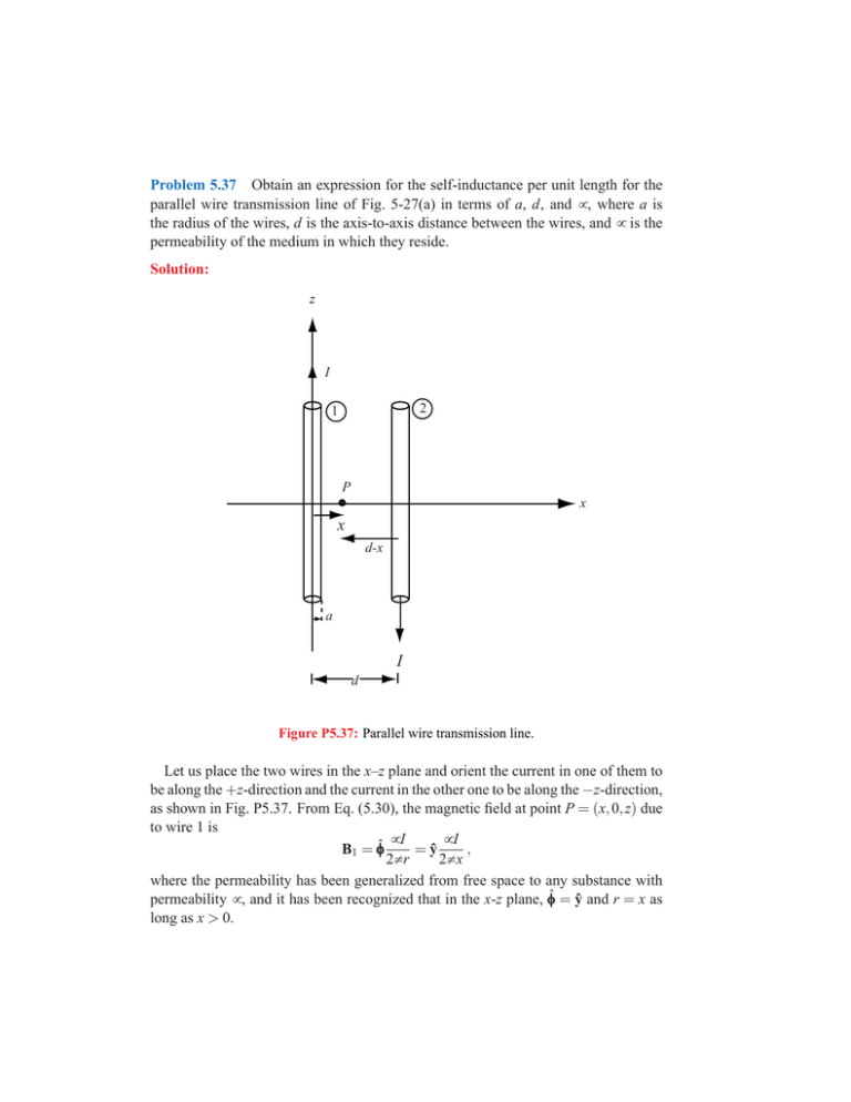
Problem 5.37 Obtain an expression for the self-inductance per unit length for the parallel wire transmission line of Fig. 5-27(a) in terms of a, d, and µ , where a is the radius of the wires, d is the axis-to-axis distance between the wires, and µ is the permeability of the medium in which they reside. Solution: z I 2 1 P x x d-x a I d Figure P5.37: Parallel wire transmission line. Let us place the two wires in the x–z plane and orient the current in one of them to be along the +z-direction and the current in the other one to be along the −z-direction, as shown in Fig. P5.37. From Eq. (5.30), the magnetic field at point P = (x, 0, z) due to wire 1 is µI µI = ŷ , B1 = φ̂φ 2π r 2π x where the permeability has been generalized from free space to any substance with permeability µ , and it has been recognized that in the x-z plane, φ̂φ = ŷ and r = x as long as x > 0. Given that the current in wire 2 is opposite that in wire 1, the magnetic field created by wire 2 at point P = (x, 0, z) is in the same direction as that created by wire 1, and it is given by µI B2 = ŷ . 2π (d − x) Therefore, the total magnetic field in the region between the wires is µ ¶ µI 1 µ Id 1 B = B1 + B2 = ŷ + . = ŷ 2π x d − x 2π x(d − x) From Eq. (5.91), the flux crossing the surface area between the wires over a length l of the wire structure is ¶ Z z0 +l Z d−a µ ZZ µ Id · (ŷ dx dz) ŷ B · ds = Φ= 2π x(d − x) z=z0 x=a S µ ¶¶¯d−a µ ¯ µ Ild 1 x ¯ ln = ¯ 2π d d −x ¶ µx=a ¶¶ µ µ µ Il a d −a = − ln ln 2π a d −a µ µ ¶ ¶ d −a d −a µ Il µ Il × 2 ln ln = = . 2π a π a Since the number of ‘turns’ in this structure is 1, Eq. (5.93) states that the flux linkage is the same as magnetic flux: Λ = Φ. Then Eq. (5.94) gives a total inductance over the length l as µ ¶ d −a Λ Φ µl ln (H). L= = = I I π a Therefore, the inductance per unit length is µ µ ¶ ¶ L µ d −a d µ ′ L = = ln ≈ ln l π a π a (H/m), where the last approximation recognizes that the wires are thin compared to the separation distance (i.e., that d ≫ a). This has been an implied condition from the beginning of this analysis, where the flux passing through the wires themselves have been ignored. This is the thin-wire limit in Table 2-1 for the two wire line.


