DCGN 381 Introduction to Electrical Circuits, Electronics and Power
advertisement
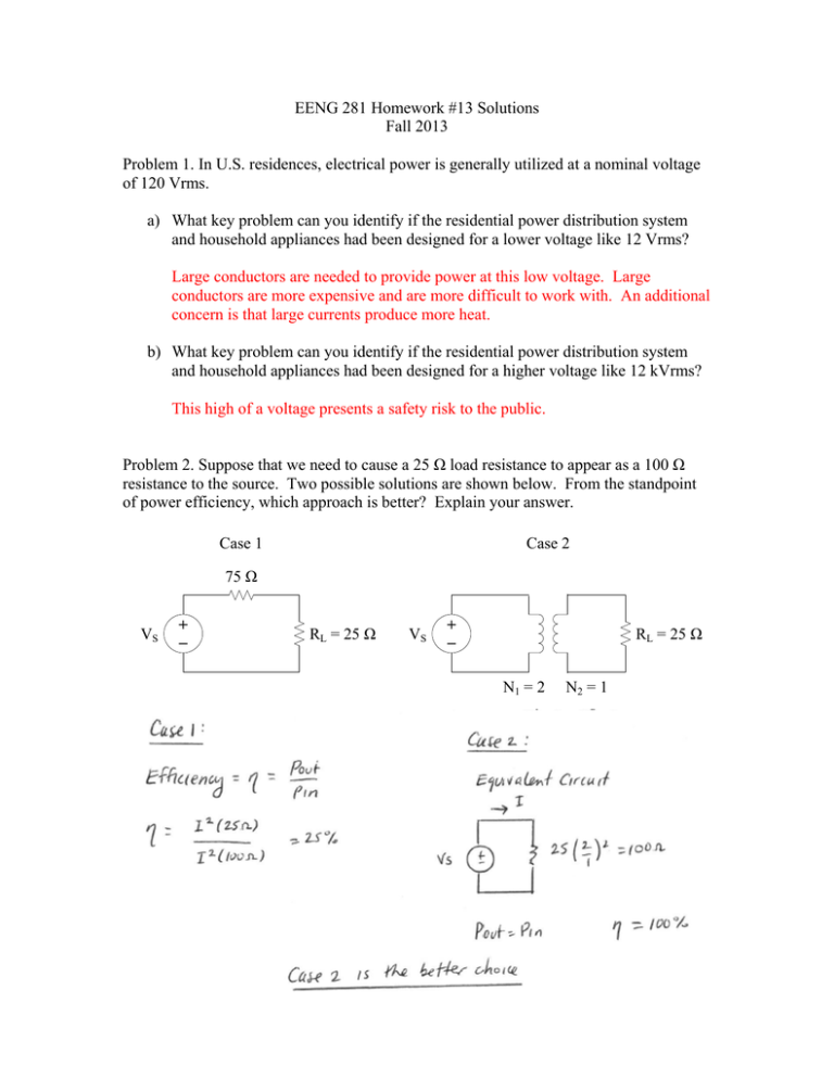
EENG 281 Homework #13 Solutions Fall 2013 Problem 1. In U.S. residences, electrical power is generally utilized at a nominal voltage of 120 Vrms. a) What key problem can you identify if the residential power distribution system and household appliances had been designed for a lower voltage like 12 Vrms? Large conductors are needed to provide power at this low voltage. Large conductors are more expensive and are more difficult to work with. An additional concern is that large currents produce more heat. b) What key problem can you identify if the residential power distribution system and household appliances had been designed for a higher voltage like 12 kVrms? This high of a voltage presents a safety risk to the public. Problem 2. Suppose that we need to cause a 25 Ω load resistance to appear as a 100 Ω resistance to the source. Two possible solutions are shown below. From the standpoint of power efficiency, which approach is better? Explain your answer. Case 1 Case 2 75 Ω VS + − RL = 25 Ω VS + − RL = 25 Ω N1 = 2 N2 = 1 Problem 3. Consider the circuit shown below. RS = 1000 Ω I1 VS = 1000 Vrms + − + V1 − N1 = 10 I2 + V2 − N2 = 1 RL = 10 Ω XL = j20 Ω Problem 4. List the three electrical hazards defined by NFPA 70E: Standard for Electrical Safety in the Workplace: 1. Shock 2. Arc Flash 3. Arc Blast Problem 5. A man accidentally let his parakeet out the door. The bird flew up to a power line and sat there. Unable to coax the bird down, the man stands on an aluminum ladder and reaches for the bird with an aluminum pole. Is there any potential danger in this situation? If so, what, and if not, why not? (Figure adapted from: Irwin, J. D. & Kerns, D. V. (1995). Introduction to Electrical Engineering. Upper Saddle River, NJ: Prentice-Hall.) The man may provide a path to ground from the power line through his body. This is a potentially fatal scenario. Problem 6. A regular household system of a single-phase, three-wire circuit allows the operation of both 120-V and 240-V, 60-Hz appliances. The household service circuitry is modeled as shown below. Calculate: The phasor currents I1, I2, and IN. I1 120 + j0 V + − 10 Ω Lamp IN 30 Ω 10 Ω 120 + j0 V + − Refrigerator I2 15 mH Kitchen Range
