Tankless Electric Water Heater
advertisement

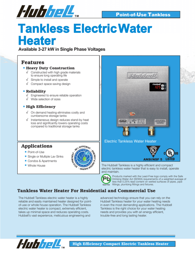
Point-of-Use Tankless Tankless Electric Water Heater Available 3-27 kW in Single Phase Voltages Features ■ Heavy Duty Construction � Constructed with high grade materials to ensure long operating life � Simple to install and operate � Compact space saving design ■ Reliability � Engineered to ensure reliable operation � Wide selection of sizes ■ High Efficiency � On demand heating eliminates costly and cumbersome storage tanks � Instantaneous design reduces stand-by heat loss and significantly lowers operating costs compared to traditional storage tanks Electric Tankless Water Heater ■ ND FRIE LY • O C ■ Point-of-Use Single or Multiple Lav Sinks Condos & Apartments Whole House EFFICIENT • SAVING • E ER ■ 8% ERGY & WA T EN ■ 9 Applications ANSI/NSF 5 The Hubbell Tankless is a highly efficient and compact electric tankless water heater that is easy to install, operate and maintain. Products marked with the Lead-Free logo comply with the Safe Drinking Water Act (SDWA) requirements of a weighted average of less that 0.25% lead content on wetted surfaces of pipes, pipe fittings, plumbing fittings and fixtures. Tankless Water Heater For Residential and Commercial Use The Hubbell Tankless electric water heater is a highly reliable and easily maintained heater designed for pointof-use or whole house operation. The Hubbell Tankless electric water heater is compact, extremely efficient, takes up minimal space and reduces operating costs. Hubbell’s vast experience, meticulous engineering and advanced technology ensure that you can rely on the Hubbell Tankless heater for your water heating needs in even the most demanding applications. The Hubbell Tankless is the right choice for your water heating needs and provides you with an energy efficient, trouble-free and long lasting heater. High Efficiency Compact Electric Tankless Heater Hubbell Tankless Features How It Works The Hubbell tankless electric water heater contains high powered heating elements that heat water only when there is demand for hot water. When hot water is needed, a built in flow sensor measures the exact flow rate, and that data combined with temperature readings at the heater’s inlet and outlet are processed by the electronic temperature controller. This data is continuously transmitted to the temperature controller, which constantly calculates the precise amount of power (kW) needed to achieve the desired temperature. A zero cross over firing signal is sent to the fast acting triacs in order to modulate the heating elements to the precise level needed to meet demand. The Hubbell tankless heater uses only as much power as is needed, while delivering accurate and consistent hot water temperature. Heater Overview - 3 Element Model Shown Inlet Thermistor Commercial Quality Heating Elements Senses cold water temperature Incoloy sheathed for long life Numeric Digital Display Electronic Temperature Controller is adjustable in 1° increments in either °F or °C Safety Thermostats Auto resetting Hi-Limit thermostats protect against over heating Solid State Switching Triac Stainless Steel Exterior Sleek design and corrosion resistant for long life Modulates heating elements 0-100% to ensure accurate temperatures and long element life Heating Chamber Power Terminal Block Universal electrical connection point All copper and bronze construction Flow Meter Measures the flow rate precisely to accurately control hot water temperature Outlet Thermistor Provides feedback to ensure consistent outlet temperature Push Fit Connections Simplifies plumbing installation HOT WATER OUT Drain Port COLD WATER IN Simplifies winterization process for seasonal installations Tankless Standard Specifications Heating Chamber: Copper and Bronze Hi-Limit: 150°F (65°C) Capacities: 3 thru 27 kW Design WP: 150 psi Orientation: Wall Mounted Design TP: 300 psi Voltage: 240 / 220 /208 Volt Elements: Incoloy 800 Phase: 1 Φ Standby Power: < 3 Watts Power Factor: 0.999 Chamber Warranty: Residential: Commercial: 5 Years 5 Years Electrical Warranty: Residential: Commercial: 3 Years 1 Years Thermal Efficiency 98% + Inlet/Outlet Size: Min/Max Flow: 3/4" Push Fit 0.2 GPM Min, 8.0 GPM Max Thermostat Range: 32 -140°F / 0-60°C 2 Enclosure: Stainless Steel Brushed Finish Approvals: cULus, UL EPH ANSI/NSF5 Max Inlet Temp.: 150°F Technical Features Temperature Controller A sophisticated electronic temperature controller with LED digital display provides the user interface. The temperature controller processes all flow and temperature data and calculates the precise amount of power needed to meet demand. Operator Control Capabilities ✓ Power Limiting: Allows the operator to reduce the power consumption by any percentage to provide installation and operational flexibility and savings. ✓ Diagnostics: Display inlet and outlet temperatures, flow rate and error codes to assist in troubleshooting. ✓ Cost Calculator: Determine the exact cost of operating the heater. Input your cost per KW·Hr and the controller displays total KW·HRs consumed, total cost of operation, and total hot water usage (shown in gallons or liters). ✓ Temperature Control: Set the digital display to the desired water temperature in °F or °C. Fully adjustable in 1° increments from 32-194°F (0-90°C). A user adjustable +/- 3° calibration feature provides additional control for superior accuracy. Full Heater Modulation Each heating element is switched on/off using a fast acting solid state triac with zero cross over firing control. This switching schema provides full modulation of each heating element, ensuring that the precise amount of heat is added to meet demand. To improve operating efficiency and component longevity, each triac is mounted to a heat sink located on the incoming supply piping so that heat generated by the triac during the switching process is dissipated into the water. Proper Power Integrity All Hubbell tankless water heaters are engineered to operate as a balanced load and operate at 0.999 Power Factor. All load switching in Hubbell tankless models is performed as zero cross over, eliminating phase angle firing interference and associated EMI issues. Full Resource Staging The Hubbell tankless control schema ensures that usage is equalized across all heating circuits. To achieve this, once the controller has calculated the precise amount of kW required, all circuits are energized in a staggered fashion such that each circuit is proportionally and independently energized and then time staggered between circuits. This Full Resource Staging Schema reduces EMI output, increases component longevity and provides highly accurate and consistent hot water temperatures. Building Management Integration Remote Control: Ability to remotely enable or inhibit the heating operation of the unit using one of the following two methods: 1. Customer supplied 24VDC signal is user configu ed for either Inhibit Mode or Normal Operation Mode. 2. Customer supplied volt free contact is user configu ed for either Inhibit Mode or Normal Operation Mode. Priority Control: An integrated SPDT potential free dry contact (NO/NC 10A @ 240VAC) energizes when the unit is heating and de-energizes when not heating. This feature is useful when it is desirable to give the water heater priority over another electrical load to ensure that both are not operational at the same time. Options A. Inlet and Outlet Valve assembly simplifies installation and includes unions, shut offs, check valve, drain ports and pressure relief valve. B. Air Separator to clear the incoming cold water of micro air bubbles, sand, dirt and rust. Recommended for use with well water systems. C. Descaler kit simplifies the process of cleaning the heater and removal of mineral deposits. D. For heaters suitable for operation with 3 phase voltages please see Hubbell model TX brochure. E. Special construction features available. Please consult factory. F. Remote Control Display allows the heater to be installed in a remote location. The 3" x 5" NEMA 4 display enclosure can be located up to 250' from the heater and gives the operator full remote control and monitoring capabilities. G. An ASSE 1070 code compliant Thermostatic mixing valve to increase the amount of hot water available. Valve is 1/2" (-UT) size and adjustable from 80-120°F. Typically used when supplying hot water to multiple lavs from a single water heater. Metric Conversions Liters x 0.2641 = Gallons Gallons x 3.79 = Liters Gallons x 0.003785 = m3 m3 x 264.2 = Gallons 1°C ∆T = 1.8°F ∆T °F = (°C x 1.8) + 32 °C = (°F - 32) x 0.556 psi x 0.06896 = Bar Bar x 14.5 = psi psi x 6.86 = kPa kPa x 0.1456 = psi Kg / cm2 x 14.28 = psi psi x 0.07 = Kg / cm2 Lbs x 0.4536 = Kg Kg x 2.2 = Lbs 3 Outline Dimensions and Model Selection 3 -18 KW Models KW Selection Chart (2 Element) KW Ratings Model Number 1 13 2 " 1 12 2 " R003-2S R005-2S R007-2S R009-2S R0011-2S R0014-2S R0016-2S R0018-2S 3 18" Withdrawal Space 12" 3 16 16 " 1 14 4 " 240V 220V 208V 3 4.5 7 9 11 14 16 18 2.5 3.7 5.8 7.5 9.2 11.7 13.4 15.1 2.2 3.3 5.2 6.7 8.2 10.5 12 13.5 Side View 9 11 16 " 9 3 16 " 3 1 16 " 3 18" 3" 6" 5 2 16 " Hot Water Outlet Pressure Drop: 3 psi @ 4 GPM 21-27 KW Models Electrical knockout 3/4" x 1" x 11/4" Cold Water Inlet Dry Weight: 16 Lbs Wet Weight: 16.5 Lbs Shipping Weight: 17 Lbs (3 Element) KW Selection Chart 17" 16" Model Number R021-3S R024-3S R027-3S 3 18" Withdrawal Space 12" KW Ratings 240V 220V 208V 21 24 27 17.6 20.1 22.6 15.7 18 20.2 Side View 3 16 16 " 1 15 16 " 1 14 4 " 9 3 16 " 3 18" 3 1 16 " 3" 1 48" 3" 6" 5 2 16 " Hot Water Outlet Pressure Drop: 3 psi @ 4 GPM 4 Electrical knockout 3/4" x 1" x 11/4" Cold Water Inlet Dry Weight: 20 Lbs Wet Weight: 20.5 Lbs Shipping Weight: 21 Lbs Heating Capacity and Amperage Chart KW Ratings at Various Voltages Model No. 240V 3 220V R003-2S 208V 2.52 2.25 4.5 R005-2S 3.78 3.37 7 R007-2S 5.88 5.2 9 R009-2S 7.56 6.7 11 R011-2S 9.24 8.2 14 R014-2S 11.76 10.5 16 R016-2S 13.44 12 18 R018-2S 15.12 13.5 21 R021-3S 17.64 15.75 24 R024-3S 20.16 18 27 R027-3S 22.68 20.25 o Heating Capability in GPM at F o Temperature Rise (°F ( FΔT) ∆T) 40°F 40∆T 0.51 0.43 0.38 0.77 0.64 0.57 1.19 1.00 0.89 1.54 1.29 1.14 1.88 1.58 1.40 2.39 2.01 1.79 2.73 2.29 2.05 3.07 2.58 2.30 3.58 3.01 2.69 4.09 3.44 3.07 4.61 3.87 3.45 60°F 60 ∆T 0.34 0.29 0.26 0.51 0.43 0.38 0.80 0.67 0.59 1.02 0.86 0.76 1.25 1.05 0.93 1.59 1.34 1.19 1.82 1.53 1.36 2.05 1.72 1.54 2.39 2.01 1.79 2.73 2.29 2.05 3.07 2.58 2.30 80°F 80 ∆T 0.26 0.21 0.19 0.38 0.32 0.29 0.60 0.50 0.44 0.77 0.64 0.57 0.94 0.79 0.70 1.19 1.00 0.90 1.36 1.15 1.02 1.54 1.29 1.15 1.79 1.50 1.34 2.05 1.72 1.54 2.30 1.93 1.73 100°F 100 ∆T 0.20 0.17 0.15 0.31 0.26 0.23 0.48 0.40 0.35 0.61 0.52 0.46 0.75 0.63 0.56 0.96 0.80 0.72 1.09 0.92 0.82 1.23 1.03 0.92 1.43 1.20 1.07 1.64 1.38 1.23 1.84 1.55 1.38 Max Amps at 100% output 1 Phase Voltages 240V 12.5 220V 208V 11.4 10.8 19 17.1 16.2 29 26.7 25 37.5 34.3 32.2 46 42 39.4 58 53.4 50.4 67 61 57.6 75 68.7 64.9 87.5 80.1 75.7 100 91.6 86.5 112 103 97.3 Note: • Alternate voltages including 277, 380, 415, 440, 575 and 600 volt available. Please consult factory for exact KW availability in these voltages. • For 3 phase voltages please reference Hubbell model TX brochure. Sizing Formulas Step 1 Voltage De-Rating Factors Solve for the unknown using formulas below. Rated Voltage Applied Voltage Variables To Solve For: KW Requirement: GPM x oF∆T x 0.1465 = KW Temperature Rise: Flow Rate: KW x 6.824 ÷ GPM KW x 6.824 ÷ oF∆T = F∆T o GPM Step 2 Choose the Tankless model with the KW rating which meets the peak demand (GPM) and required temperature rise (oF∆T) for your application. De-Rating Factor 240 V 230 V 92% 240 V 220 V 84% 240 V 208 V 75% When the actual supply voltage (applied voltage) is different than the design voltage (rated voltage) the resulting KW output will be affected. Please see the chart for typical voltage de-rating factors, or use the following formula. Applied Voltage2 Rated Voltage2 X Rated KW = KW output at applied voltage Step 3 Choose the supply voltage available. Note the total amperage draw of the unit and verify availability. 5 Master Specification: Point-of-Use Tankless Job N ame eng ineer / Architect Representative contractor GENERAL Provide a quantity of packaged type instantaneous electric tankless water heater(s) Model No. as manufactured by HUBBELL Electric Heater Co., Stratford, CT. The entire unit is packaged ready for plumbing and electrical service connections and shall bear the cULUs listing mark certifying the entire unit to UL499, CSA C22.2 No. 64-M91 and UL EPH Sanitation listed to ANSI/NSF Standard 5. HEATING CHAMBER The heating chamber shall be all Sil-brazed copper and bronze construction. A plastic heating chamber shall not be acceptable. Water heater heating chamber shall be rated for a maximum allowable working pressure of 150 psi. The heating chamber and all electrical controls shall be completely enclosed in a stainless steel case. HEATING CAPACITY KW which will heat GPM of water at °F rise The tankless heater shall be rated at ( ° to °F ). Heaters that require the use of a flow estrictor or specialized aerator shall not be acceptable. ELECTRICAL The heater shall be designed to operate at volts, single phase, 50/60Hz and will draw amps only when operating at full power. The immersion heating elements shall be high quality incoloy sheathed and sized to obtain the rated capacity. Each element is to be operated using zero cross over solid state controls. The heating elements shall be fully modulated from 0-100% to provide precise temperature control through the full range of flows. A Hi-Limit thermostat with automatic eset shall be factory installed to disconnect each heating element in the event of an over-temperature condition. An electronic digital display temperature controller shall be user adjustable in 1° increments in either °F or °C and shall display flow rate, outlet temperatu e, inlet temperature and provide error indication. A turbine-type flow meter shall be factory installed to p ovide precise temperature control for water flows as low as 0.2 GPM up to a maximum flow of 8 GPM. Heaters that equire greater than 0.2 GPM flow for actuation or restrict flow shall not be acceptable. WARRANTY Hubbell shall warranty all electrical components against defects in workmanship and material for a period of one (1) year from date of start-up and the heating chamber for a full five (5) years f om date of start-up (for residential service, five (5) years heating chamber and th ee (3) years electrical), provided that the unit is started within three (3) months of date of shipment and installed and operated within the scope of the heater's design and operating capability. Labor is not covered under warranty. Each heater shall be shipped with a complete set of installation and operating instructions including spare parts list and approved drawings. All fabrication and assembly shall be performed in the U.S.A. OPTIONS In addition, the tankless electric water heater shall be supplied with the following options: Option Option Option ISO 9001:2008 ISO Made in the U.S.A. Committed to continuous improvement... Continuing research results in product improvement; therefore specifications are subject to change without notice. For the most updated information, consult the factory directly. The Electric Heater Company ■ P.O. Box 288 ■ Stratford, CT 06615-0288 ■ Phone: 203-378-2659 info@hubbellheaters.com ■ www.hubbellheaters.com ■ Fax: 203-378-3593 [REV C]

