Round and Square Trim Installation
advertisement
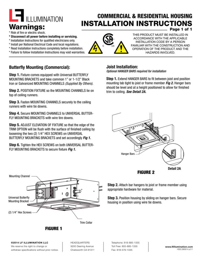
COMMERCIAL & RESIDENTIAL HOUSING INSTALLATION INSTRUCTIONS Warnings: * Risk of fire or electric shock. * Disconnect all power before installing or servicing. * Installation Instructions for qualified electricians only. * Install per National Electrical Code and local regulations. * Read Installation Instructions completely before installation. * Failure to follow Installation Instructions may void warranties. Page 1 of 1 ® C US THIS PRODUCT MUST BE INSTALLED IN ACCORDANCE WITH THE APPLICABLE INSTALLATION CODE BY A PERSON FAMILIAR WITH THE CONSTRUCTION AND OPERATION OF THE PRODUCT AND THE HAZARDS INVOLVED. Joist Installation: Butterfly Mounting (Commercial): Step 1. Fixture comes equipped with Universal BUTTERFLY MOUNTING BRACKETS and take common 1” or 1-1/2” Black Iron or Galvanized MOUNTING CHANNELS (Supplied By Others). Step 2. POSITION FIXTURE so the MOUNTING CHANNELS lie on top of ceiling runners. Optional HANGER BARS required for installation Step 1. Extend HANGER BARS to fit between joist and position mounting tab tight to joist or frame member Fig 2. Hanger bars should be level and at a height positioned to allow for finished trim to ceiling. See Detail 2A. Step 3. Fasten MOUNTING CHANNELS securely to the ceiling runners with wire tie downs. Step 4. Secure MOUNTING CHANNELS to UNIVERSAL BUTTERFLY MOUNTING BRACKETS with wire tire downs. Step 5. ADJUST ELEVATION OF FIXTURE so that the edge of the TRIM OPTION will be flush with the surface of finished ceiling by loosening the two (2) 1/4” HEX SCREWS on UNIVERSAL BUTTERFLY MOUNTING BRACKETS and set accordingly Fig 1. Step 6. Tighten the HEX SCREWS on both UNIVERSAL BUTTERFLY MOUNTING BRACKETS to secure fixture Fig 1. Hanger Bars FIGURE 2 Mounting Channel Detail 2A Step 2. Attach bar hangers to joist or frame member using appropriate hardware for material. Step 3. Position housing by sliding on hanger bars. Secure Universal Butterfly Mounting Bracket housing in position using wire tie downs. (2) 1/4” Hex Screws Trim Collar FIGURE 1 ©2014 LF ILLUMINATION LLC HEADQUARTERS Telephone: 818-885-1335 We reserve the right to change or 9200 Deering Avenue Toll Free: 855-885-1335 withdraw specifications without prior notice. Chatsworth CA 91311 Fax: 818-576-1335 www.lfillumination.com HSG 090914 p1/1 MOLI TRIM Square and Round INSTALLATION INSTRUCTIONS Warnings: * Risk of fire or electric shock. * Disconnect all power before installing or servicing. * Installation Instructions for qualified electricians only. * Install per National Electrical Code and local regulations. * Read Installation Instructions completely before installation. * Failure to follow Installation Instructions may void warranties. ® C US THIS PRODUCT MUST BE INSTALLED IN ACCORDANCE WITH THE APPLICABLE INSTALLATION CODE BY A PERSON FAMILIAR WITH THE CONSTRUCTION AND OPERATION OF THE PRODUCT AND THE HAZARDS INVOLVED. FIGURE 1 1. Connect the power supply / electrical panel using the prewired quick connects. FIGURE 2 2. Insert power supply / electrical panel into housing going through the trim collar with power supply inserted into electrical compartment. FIGURE 3 FIGURE 4 3. On the trim, turn torsion springs inward and slide the trim into the housing collar. 4. Push trim into the housing collar to set in place. ©2014 LF ILLUMINATION LLC HEADQUARTERS Telephone: 818-885-1335 We reserve the right to change or 9200 Deering Avenue Toll Free: 855-885-1335 withdraw specifications without prior notice. Chatsworth CA 91311 Fax: 818-576-1335 www.lfillumination.com Moli trim insert 052014

