Physics 326 - Lab 4 7/25/16
advertisement

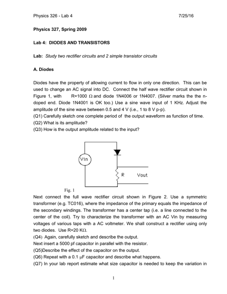
Physics 326 - Lab 4 7/25/16 Physics 327, Spring 2009 Lab 4: DIODES AND TRANSISTORS Lab: Study two rectifier circuits and 2 simple transistor circuits A. Diodes Diodes have the property of allowing current to flow in only one direction. This can be used to change an AC signal into DC. Connect the half wave rectifier circuit shown in Figure 1, with R=1000 and diode 1N4006 or 1N4007. (Silver marks the the n- doped end. Diode 1N4001 is OK too.) Use a sine wave input of 1 KHz. Adjust the amplitude of the sine wave between 0.5 and 4 V (i.e., 1 to 8 V p-p). (Q1) Carefully sketch one complete period of the output waveform as function of time. (Q2) What is its amplitude? (Q3) How is the output amplitude related to the input? Fig. 1 Next connect the full wave rectifier circuit shown in Figure 2. Use a symmetric transformer (e.g. TC016), where the impedance of the primary equals the impedance of the secondary windings. The transformer has a center tap (i.e. a line connected to the center of the coil). Try to characterize the transformer with an AC Vin by measuring voltages of various taps with a AC voltmeter. We shall construct a rectifier using only two diodes. Use R=20 K Q4Again, carefully sketch and describe the output. Next insert a 5000 pf capacitor in parallel with the resistor. (Q5)Describe the effect of the capacitor on the output. (Q6) Repeat with a 0.1 F capacitor and describe what happens. (Q7) In your lab report estimate what size capacitor is needed to keep the variation in 1 Physics 326 - Lab 4 7/25/16 voltage to less than 1%. Fig. 2 B. Transistors. The transistor is one of the most important components of modern electronics. In most applications individual transistors are not used, rather, they are the heart of integrated circuits (which may contain thousands of transistors in a single chip). Here we will construct two simple circuits to look at basic transistor behavior. The first measurement demonstrates how a transistor can act to transform a poor voltage source into a relatively good one. First set up a two resistor voltage divider (see Lab 1) with each resistor (i.e., R1 and R2) equal to 1 KUse a DC input voltage of +12 V. (Q8) Measure the DC input voltage and that across R2. (Q9) Add a ~500 load resistor in parallel with R2 and again measure the voltage. Plot the output voltage as a function of output current through the load resistor (You have two data points, and since the relationship is linear, you can just connect the points.). What is the output impedance of the voltage divider (given by the slope -dVout/dIout)? Remove the ~500 resistor. Next make the circuit shown in Figure 3 by connecting the node between R1 and R2 to the base of the NPN transistor (2N3904 or MPS3392). Use R1, R2, and Re equal to 1 K. (Q10) Measure the output voltage Vout , the voltage across Re. (Q11) Next add a ~500 load resistor in parallel with Re and again measure the output voltage. Plot Vout vs. Iout in the same graph as the voltage divider, connecting the two data points. 2 Physics 326 - Lab 4 7/25/16 (Q12) Calculate the output impedance of the circuit (given by the slope -dVout/dIout).. (Q13) Explain your observations in your lab report. Fig. 3 Next connect the circuit shown in Fig. 4 which acts as a simple current source.. Let the load resistance RL equal 500, 1000, 2000, 3000, and 5000 (Q14) Measue Vout and determine the current IL through RL in each case. Plot IL vs RL. (Q15) Explain your measurements. Why does the current through the load resistor depend on RL the way it does? Fig. 4 3


