LAT X-LAT Peer Review RFA Response #3 Action Requested:

LAT X-LAT Peer Review RFA Response #3
Action Requested:
Recommend developing a torque sequence for bolting X-LAT plate to electronics boxes to minimize interface stresses. Torque fasteners in several steps? Torque from center of
X-LAT plate out? Or from alignment pins out?
Reason:
Significant interface stresses could result from non-optimum torquing of fasteners.
Response:
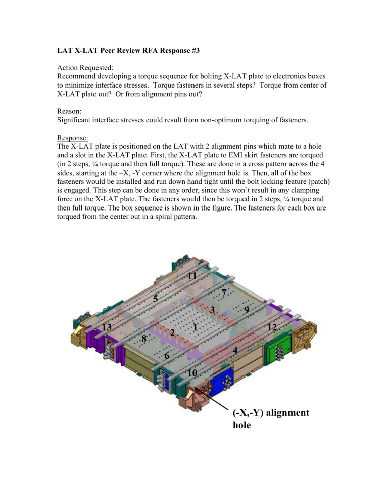
The X-LAT plate is positioned on the LAT with 2 alignment pins which mate to a hole and a slot in the X-LAT plate. First, the X-LAT plate to EMI skirt fasteners are torqued
(in 2 steps, ¼ torque and then full torque). These are done in a cross pattern across the 4 sides, starting at the –X, -Y corner where the alignment hole is. Then, all of the box fasteners would be installed and run down hand tight until the bolt locking feature (patch) is engaged. This step can be done in any order, since this won’t result in any clamping force on the X-LAT plate. The fasteners would then be torqued in 2 steps, ¼ torque and then full torque. The box sequence is shown in the figure. The fasteners for each box are torqued from the center out in a spiral pattern.
13
11
5
8
6
2
1
10
3
7
9
4
12
(-X,-Y) alignment hole


