Keck Next Generation Adaptive Optics Real Time Controller (RTC) Introduction
advertisement

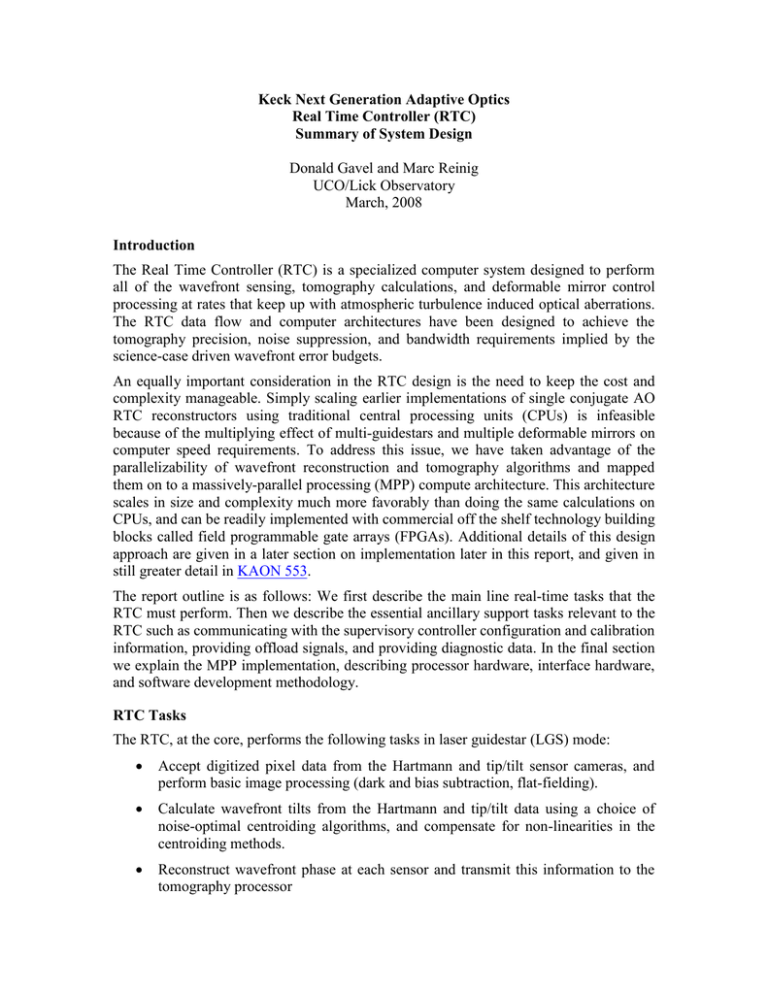
Keck Next Generation Adaptive Optics Real Time Controller (RTC) Summary of System Design Donald Gavel and Marc Reinig UCO/Lick Observatory March, 2008 Introduction The Real Time Controller (RTC) is a specialized computer system designed to perform all of the wavefront sensing, tomography calculations, and deformable mirror control processing at rates that keep up with atmospheric turbulence induced optical aberrations. The RTC data flow and computer architectures have been designed to achieve the tomography precision, noise suppression, and bandwidth requirements implied by the science-case driven wavefront error budgets. An equally important consideration in the RTC design is the need to keep the cost and complexity manageable. Simply scaling earlier implementations of single conjugate AO RTC reconstructors using traditional central processing units (CPUs) is infeasible because of the multiplying effect of multi-guidestars and multiple deformable mirrors on computer speed requirements. To address this issue, we have taken advantage of the parallelizability of wavefront reconstruction and tomography algorithms and mapped them on to a massively-parallel processing (MPP) compute architecture. This architecture scales in size and complexity much more favorably than doing the same calculations on CPUs, and can be readily implemented with commercial off the shelf technology building blocks called field programmable gate arrays (FPGAs). Additional details of this design approach are given in a later section on implementation later in this report, and given in still greater detail in KAON 553. The report outline is as follows: We first describe the main line real-time tasks that the RTC must perform. Then we describe the essential ancillary support tasks relevant to the RTC such as communicating with the supervisory controller configuration and calibration information, providing offload signals, and providing diagnostic data. In the final section we explain the MPP implementation, describing processor hardware, interface hardware, and software development methodology. RTC Tasks The RTC, at the core, performs the following tasks in laser guidestar (LGS) mode: Accept digitized pixel data from the Hartmann and tip/tilt sensor cameras, and perform basic image processing (dark and bias subtraction, flat-fielding). Calculate wavefront tilts from the Hartmann and tip/tilt data using a choice of noise-optimal centroiding algorithms, and compensate for non-linearities in the centroiding methods. Reconstruct wavefront phase at each sensor and transmit this information to the tomography processor Kolmogorov filter Layer heights Guide star height Wavefront Wavefront Sensors Wavefront Sensors Wavefront Sensors Sensors Image Image Processors Image Processors Image Processors Processors Tomography Unit Centroid algorithm r0, guidstar brightness, Guidestar position Precondition Cn2 profile FT-1 X FT Wavefront Wavefront Sensors Wavefront Sensors DM Sensors Projection DM conjugate altitude Backpropagate + X Actuator influence function Volumetric OPD estimates FT Image Image Processors Image Processors Deformable Processors Mirrors Postcondition Aperture WFS data Image Image Processors Image Processors DM Processors Fit FT-1 Forwardpropagate Aperture Figure 1. Schematic of the data flow and parallel processing for multi-guidestar tomography Use cone-beam projection tomography techniques to reconstruct the threedimensional volume of atmospheric index-of-refraction variations above the telescope and over the field of view of interest, given the wavefronts from various directions as measured by each wavefront sensor. This algorithm also taske inputs from the tip/tilt and tip/tilt/focus/astigmatism sensors to break volume solution ambiguities inherent in laser wavefront measurements. Integrate through the volume of index estimates along paths to the science instruments – either on-axis for the narrow field science modes, or along up to 6 different directions for the deployable integral field spectrograph science mode. Compensate for deformable mirror influence functions and nonlinearities, deriving voltage commands for the DMs given desired wavefront distortion corrections to be placed on them. Split the control between commands to the tip/tilt mirror, low-order (woofer) DM, and high order (tweeter) DMs. Incorporate control compensation dynamics to keep the system stable and achieving a given temporal bandwidth. In LGS mode the RTC also computes high-order wavefront control commands for DMs in the tip/tilt sensors, sharpening the IR tip/tilt stars. In natural guidestar (NGS) mode, the RTC acts as a traditional single conjugate AO system. It takes inputs from one natural guidestar wavefront sensor, reconstructs the wavefront, and computes commands to be split up amongst the tip/tilt mirror, woofer DM, and tweeter DM in the narrow field science path. All these RTC tasks take place at the frame rate of the fastest wavefront sensor camera, up to 2,000 frames per second. As shown in the Figure 1 schematic, large chunks of compute tasks are associated with either wavefront sensors or DMs and thus can be parallelized across them. Thus some of the dedicated processing units will be assigned specifically to hardware. Furthermore, algorithms within the subunits, as well as within the tomography unit itself, are highly parallelizable when implemented in the Fourier domain, and thus will each map onto an MPP architecture as described earlier. Parametric Input, Optimization, and Reconfigurability Minimum Variance Reconstruction Optimization The RTC algorithm computes the statistical minimum variance solutions for wavefronts at each science instrument, given the measured wavefront data from the guidestars. The minimum variance solution depends on certain a-priori data, which the RTC accepts as parametric input. These include: Volumetric turbulence strength (Cn2 profile, discretized at layers) Number of layers of turbulence Brightnesses of guidestars Wind speeds at layers Cn2 can be provided either as a-priori input, or as derived from external measurements, for example, from a MASS/DIMM sensor. The preparation and processing of this data is left to the external supervisory control system; the RTC simply takes in a set of normalized Cn2 strength numbers, one per layer, at a rate that is slow (say once/second) with respect to the real-time tasks. As an option, the RTC’s tomography engine will provide statistical average rms aberrations resolved by layer, which can be used to adjust Cn2 profile numbers dynamically. Similarly, wind speeds can be incorporated from external data or deduced internally from past histories of estimates. Calibration Parameters Truth wavefront sensors will provide long-term average wavefront data designed to normalize out systematic biases due to either non-common path optical aberration or Hartmann sensor biases due to variations in the sodium layer thickness and altitude. The RTC will process these wavefront sensor data like any other wavefront sensor and use the results to adjust zero-set points in the overall reconstructor. In a like manner, prior measurements will have determined calibration set points for each wavefront sensor, giving the definition of a “flat” wavefront for each sensor. The set points for LGS wavefront sensors will depend on field position and zenith angle. Thus the supervisory control, with knowledge of the telescope and AO system configuration, will periodically update the RTC wavefront sensor subprocessors as to which parameter set to be applying to the wavefront reconstruction. Reconfiguration The processing units and algorithm will be made reconfigurable to allow for each of the observing modes envisioned for NGAO. Configuration parameters include: Number and field-positions of laser guidestars Number and field-positions of tip/tilt guidestars Field position of TTFA (tip/tilt/focus/astigmatism) sensor Field positions of deployable integral field science wavefront correctors Furthermore, the scalloped pupil of the Keck primary mirror will rotate with respect to the wavefront sensors and DMs in some science observing scenarios. The wavefront and tomography reconstructors utilizes a model pupil as a “valid data” mask, so this model will be set and updated at the appropriate rate within the RTC. Interfaces Offloading The RTC will provide offload signals to the telescope so that high speed wavefront controllers don’t saturate. The offload signals flow to the non-RTC supervisory controller at a relatively low data rate, on the order once per second. Offloading signals include: Tip/tilt to the telescope guider Focus to the secondary piston Other low order modes TBD to the telescope primary segment control system Diagnostics and Telemetry Diagnostic data is defined as data intended for monitoring the health of the RTC and AO system, and for display to the operator. Centroid data from wavefront sensors, signals going to DMs, and other indicators are transmitted at relatively low, human readable, data rates to the external systems. Telemetry data is defined as up to full-frame rate streaming of portions or all of the intermediate data to high-speed data capture units. This data is useful for a number of post processing tasks such as Debugging or tuning of parameters Analysis of seeing conditions and performance of the AO system Point spread function determination Data that would be streamed for data capture include: All wavefront sensor centroids, intensities, and wavefront sensor reconstructed phases All tip/tilt and TTFA sensor centroids and intensities All commands to the DMs and tip/tilt mirrors All tomography volume estimate data Ancillary information associated with the operations so as to be able to reconstruct the state of the RTC at the time, including internal data tables, Cn2 numbers, wind numbers, calibration sets etc. Additional data storage capability will be needed to record full frame rate raw pixel data from the wavefront and tip/tilt sensors. Command State The RTC at any time will be operating in one of a number of possible states. Examples of such states include: Narrow field science LGS AO control (hybrid closed loop on the woofer and open loop on the narrow field tweeter and tip/tilt and TTFA tweeters) Wide field science LGS AO control (hybrid closed loop on the woofer and open loop on the deployable IFS unit tweeters and tip/tilt and TTFA tweeters) Narrow field science NGS AO control (closed loop on the woofer and tweeter) Control on tip/tilt only Calibration modes (for alignment/registration, push matrix generation, linearity calibrations) Uncontrolled or idle, with static values as loaded for the DMs and tip/tilt mirrors. The supervisory control system will transmit the state transitions to the RTC which will configure itself accordingly (and also report back its state on demand). The maintenance of state transition rules will be the responsibility of the supervisory control system. Additional flags will be maintained for turning on and off various diagnostic and telemetry streams. Implementation Algorithms Algorithms for wavefront phase reconstruction from Hartmann slope data have been analyzed since the beginning days of adaptive optics. We anticipate using a modern fastiterative technique such as the ones described in references 3 and 4. Such techniques can take advantage of parallelism if they are implemented in the Fourier domain. Regularizations taking into account the signal-to-noise of the measurement and filters for suppressing the waffle mode can also be implemented in the Fourier domain. The pupil boundary conditions (outside of which the measurements must not be assumed as zero but allowed to be free variables) force the algorithm to be iterative as described in the above references, but 3-5 iterations using a Fourier-domain pre-conditioned conjugate gradient (FD-PCG) method have been shown to be adequate for meeting our error budget. Inverse tomography algorithms using wavefront measurements from multiple directions have been developed recently (references 4 and 5). These methods are also made parallel through the use of the Fourier domain but again must be iterated because of the finite spatial extent of the pupil-apertured data. Again, the FD-PCG method has proven adequately stable and rapidly converging in simulation studies (KAON 475). Finally, fitting the deformable mirror to the desired wavefront correction can be accomplished with parallel processor implementations that carry an inverse model of each DM. MEMS open loop control is decoupled into a linear cross-coupling, which is solvable in the Fourier domain, and independent nonlinear functions for each actuator, solvable with nonlinear lookup tables in parallel. The MEMS are repeatible go-to devices and this open-loop model has been proven to be quite accurate (see reference 7). The woofer DM, likely a piezo-actuator device with cross-coupling and hysteretic effects, will be controlled via a linear Fourier domain deconvolution only. We will rely on the fact that this mirror is in “closed loop” (upstream of the wavefront sensors) and so any residual mis-fitting will be measured and sent to the more accurately responding tweeters. Bandwidth shouldn’t suffer because the woofer is correcting the lower order, and hence slower evolving, atmospheric modes. More details on algorithm implementation are given in KAON 553. Hardware The multi-processor units are implemented as banks of field-programmable gate arrays (FPGAs) arranged on custom circuit boards. The technology of FPGA programming has advanced to the point that the design and configuration of these boards, intimately coupled to the algorithm distribution on the processor chips themselves and data flow needs, is accomplished entirely using standardized computer aided design and simulation tools. The details of distributing the NGAO RTC architecture onto these processor units are given in KAON 533, sections 4 and 5. The processor units end up being many repetitions of identical processing elements, making them interchangeable and therefore easy to spare. Except for specialized I/O interfaces, the boards can be configured to process wavefront sensor data, do a piece of the inverse tomography, or process DM commands. Hardware Interfaces High throughput I/O must be used to get data from wavefront sensors to processor units and DM command data to the D/A converter hardware associated with each DM or tip/tilt mirror. Similarly, high throughput I/O must be used to get telemetry data to data storage units. For the most part, industry standard hardware is now commonly available that will handle our anticipated data rates, and an industry standard protocol (LVDS) is called out in the conceptual design. These data interconnects will be implemented on reliable high speed interconnects, such as fiber optic links. Programming and Design Process There are a number of FPGA manufacturers and each has commercial design packages to aid in the design of the programming and interconnections. MPP programming is in common practice today in industry and the required skills are taught in university computer and electrical engineering courses. Physical Implementation Space, power usage, and thermal load considerations are taken into account in the design. We have estimates of these for the conceptual NGAO RTC implementation (KAON 533 Table 5-6) which will be refined as we make trades and design choices in the later system design phases. The physical parameters are expected to be compatible with locating the RTC in a separate electronics enclosure located on the Nasmyth platform. References 1. KAON 553, M. Reinig, M. Fischler, D. Gavel, Keck Next Generation Adaptive Optics Real Time Controller (RTC) Hardware and Algorithms, January, 2008. 2. KAON 475, Donald Gavel and Chris Neyman, Tomography Codes Comparison and Validation, May 2007. 3. Vogel, C. R.; Yang, Q., Multigrid algorithm for least-squares wavefront reconstruction, Applied Optics IP, vol. 45, Issue 4, pp.705-715, (2006). 4. Gilles, Luc; Ellerbroek, Brent L.; Vogel, Curtis R., Preconditioned conjugate gradient wave-front reconstructors for multiconjugate adaptive optics, Applied Optics, Volume 42, Issue 26, pp. 5233-5250, (2003). 5. Gavel, Donald T, Tomography for multiconjugate adaptive optics systems using laser guide stars, Advancements in Adaptive Optics, Proceedings of the SPIE, Volume 5490, pp. 1356-1373 (2004) 6. Gavel, Donald; Reinig, Marc; Cabrera, Carlos, Fast hardware implementation of tomography for multi-guidestar adaptive optics, Astronomical Adaptive Optics Systems and Applications II, Proceedings of the SPIE, Volume 5903, pp. 138147 (2005). 7. Morzinski, Katie M.; Gavel, Donald T.; Norton, Andrew P.; Dillon, Daren R.; Reinig, Marco R., Characterizing MEMS deformable mirrors for open-loop operation: high-resolution measurements of thin-plate behavior, MEMS Adaptive Optics I,. Proceedings of the SPIE, Volume 6888, pp. 68880S-68880S-12 (2008).

