Written Preliminary Exam COMPUTATIONAL MECHANICS Spring 2006
advertisement

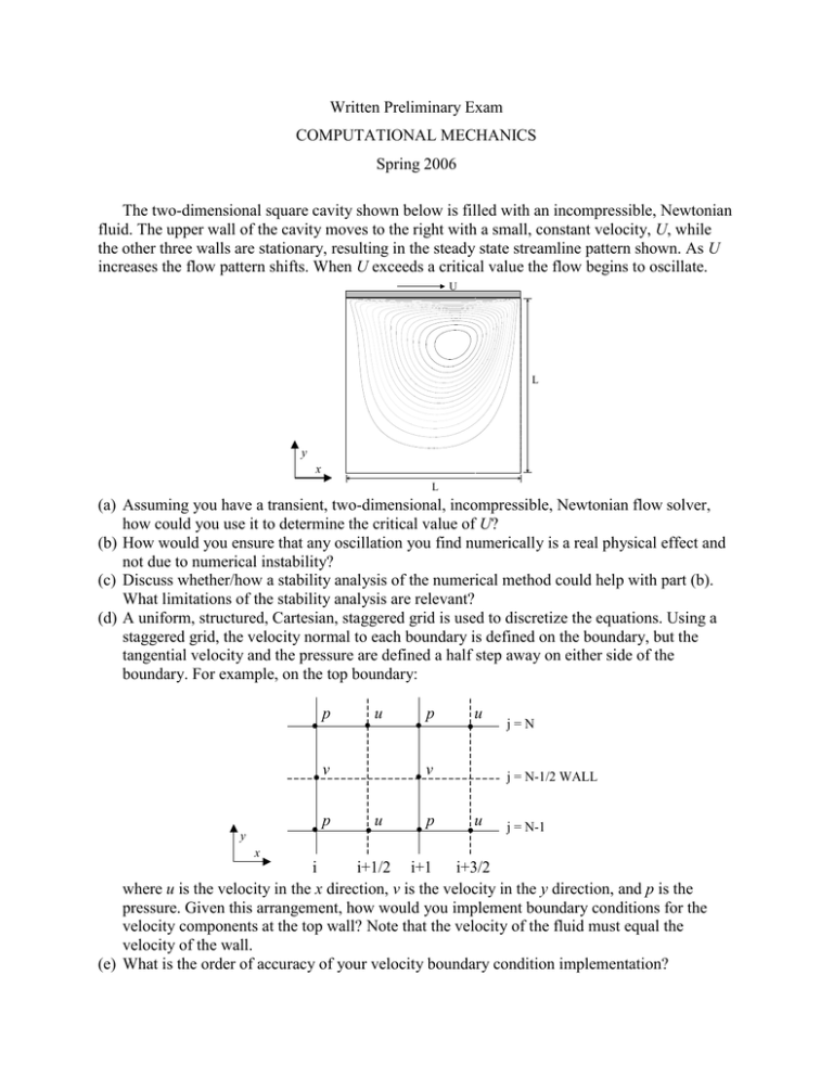
Written Preliminary Exam COMPUTATIONAL MECHANICS Spring 2006 The two-dimensional square cavity shown below is filled with an incompressible, Newtonian fluid. The upper wall of the cavity moves to the right with a small, constant velocity, U, while the other three walls are stationary, resulting in the steady state streamline pattern shown. As U increases the flow pattern shifts. When U exceeds a critical value the flow begins to oscillate. Frame 001 10 Oct 2001 Converted Plot3D Dataset U L y x L (a) Assuming you have a transient, two-dimensional, incompressible, Newtonian flow solver, how could you use it to determine the critical value of U? (b) How would you ensure that any oscillation you find numerically is a real physical effect and not due to numerical instability? (c) Discuss whether/how a stability analysis of the numerical method could help with part (b). What limitations of the stability analysis are relevant? (d) A uniform, structured, Cartesian, staggered grid is used to discretize the equations. Using a staggered grid, the velocity normal to each boundary is defined on the boundary, but the tangential velocity and the pressure are defined a half step away on either side of the boundary. For example, on the top boundary: p u v p y p u v u p j=N j = N-1/2 WALL u j = N-1 x i i+1/2 i+1 i+3/2 where u is the velocity in the x direction, v is the velocity in the y direction, and p is the pressure. Given this arrangement, how would you implement boundary conditions for the velocity components at the top wall? Note that the velocity of the fluid must equal the velocity of the wall. (e) What is the order of accuracy of your velocity boundary condition implementation? (f) Using a projection method, the difference between the intermediate velocity components, u* and v*, and the velocity components at the new time level, un+1 and vn+1, are related to the pressure as follows: 2t n 1 pi 1, j pin, j 1 u in11/ 2, j u i*1 / 2, j x 2t n 1 pi , j 1 pin, j 1 vin, j 11 / 2 vi*, j 1 / 2 y If the same boundary conditions are applied to the intermediate velocity components as to the actual velocity components, use these expressions to determine an appropriate boundary condition for the pressure at the top wall.


