Episode 228-4: Measuring the stiffness of a material (Word, 59 KB)
advertisement

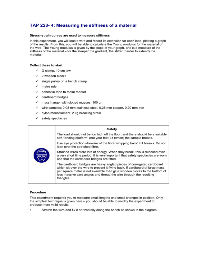
TAP 228- 4: Measuring the stiffness of a material Stress–strain curves are used to measure stiffness In this experiment, you will load a wire and record its extension for each load, plotting a graph of the results. From this, you will be able to calculate the Young modulus for the material of the wire. The Young modulus is given by the slope of your graph, and is a measure of the stiffness of the material – for the steeper the gradient, the stiffer (harder to extend) the material. Collect these to start G clamp, 10 cm jaw 2 wooden blocks single pulley on a bench clamp metre rule adhesive tape to make marker cardboard bridges mass hanger with slotted masses, 100 g wire samples: 0.08 mm stainless steel, 0.28 mm copper, 0.20 mm iron nylon monofilament, 2 kg breaking strain safety spectacles Safety The load should not be too high off the floor, and there should be a suitable soft ‘landing platform’ (not your feet!) if (when) the sample breaks. Use eye protection –beware of the fibre ‘whipping back’ if it breaks. Do not lean over the stretched fibre. Strained wires store lots of energy. When they break, this is released over a very short time period. It is very important that safety spectacles are worn and that the cardboard bridges are fitted. The cardboard bridges are heavy angled pieces of corrugated cardboard which sit over the wire to prevent it flying back. If cardboard of large mass per square metre is not available then glue wooden blocks to the bottom of less massive card angles and thread the wire through the resulting triangles. Procedure This experiment requires you to measure small lengths and small changes in position. Only the simplest technique is given here – you should be able to modify the experiment to produce more valid results. 1. Stretch the wire and fix it horizontally along the bench as shown in the diagram. wooden blocks cardboard bridges wire marker rule load 2. Make a marker from adhesive tape and attach it to the wire so that it is at least 2 m from the clamp and about 50 cm from the pulley. The marker should line up with the metre rule, so it can be used to measure the extension of the wire. Make a loop in the end of the wire to be loaded, to hang the weights from (a knot will weaken it). 3. Measure and record the original length from the clamp to the marker, with a small (1 N) load to stretch out the wire. 4. Increase the load gradually in steps of 1 N until the wire snaps. Record the load and the corresponding extension in each case. Calculating the Young modulus 1. 2 –6 2 Convert your readings of load into stress: (1 mm = 10 m ) Convert the readings of extension into strain: both extension and original length being measured in the same units. 2. Now plot stress (y axis) against strain (x axis). 3. Find the slope of your graph to obtain a value for the Young modulus. Compare it to the value given in the database. TAP 228-3: Materials database Practical advice This version of the tensile testing could be extended to materials such as cotton thread or hair if the diameter could be estimated or measured using a micrometer. Point out features such as necking – the localised narrowing of the wire before fracture – and if time permits, examine the fracture surfaces with a magnifying glass. Safety The load should not be too high off the floor, and there should be a suitable soft ‘landing platform’ (not your feet!) if (when) the sample breaks. Use eye protection –beware of the fibre ‘whipping back’ if it breaks. Do not lean over the stretched fibre. Strained wires store lots of energy. When they break this is released over a very short time period. It is very important that safety spectacles are worn and that the cardboard bridges are fitted. The cardboard bridges are heavy angled pieces of corrugated cardboard which sit over the wire to prevent it flying back. If cardboard of large mass per square metre is not available then glue wooden blocks to the bottom of less massive card angles and thread the wire through the resulting triangles. External references This activity is taken from Advancing Physics Chapter 4, 150E


