Episode 416-6: Transformers (Word, 108 KB)
advertisement

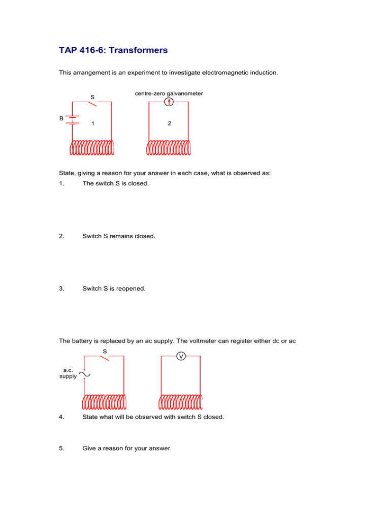
TAP 416-6: Transformers This arrangement is an experiment to investigate electromagnetic induction. centre-zero galvanometer S B 1 2 State, giving a reason for your answer in each case, what is observed as: 1. The switch S is closed. 2. Switch S remains closed. 3. Switch S is reopened. The battery is replaced by an ac supply. The voltmeter can register either dc or ac S V a.c. supply 4. State what will be observed with switch S closed. 5. Give a reason for your answer. 6. Door bells in houses are often connected to the mains electricity supply through a step-down transformer. Here are two circuits to do this. A mains input on / off bell push output transformer bell B mains input transformer output bell magnetic bell-push operating normally-open reed switch Which circuit do you consider to be less expensive to operate once it has been installed? Explain your choice. 7. In petrol engines, the fuel is ignited by a spark across a gap which must be less than about 0.60 mm. To establish the field necessary for this spark, voltages of up to 40 kV are needed, using only a 12 V battery. To achieve this, two coils are wound around the same iron core. 12 V spark gap contact breaker secondary coil primary coil iron core The secondary coil is in series with the spark gap. The primary coil is in series with the battery and a contact breaker. When the primary circuit is broken, a spark is produced. The capacitor prevents sparking across the contact breaker. Explain why a large voltage is induced when the contact with the battery is broken. 8 Many home electrical devices, such as televisions, refrigerators and hi-fi systems, incorporate transformers to step down the supply voltage. (a) An ideal transformer with a primary coil of 3000 turns provides a 9 V ac output when the input is 230 V ac. How many turns must there be on the secondary coil? (b) No transformer is 100% efficient, although most are nearly so. State two effects that may in practice reduce the efficiency of a transformer. (c) Explain why a transformer cannot provide an output of 20 V dc when connected to a car battery whose emf is 12 V. Practical advice Beginning with basic ideas, this question set develops understanding of everyday devices such as domestic door-bells and the induction coil used in ignition systems for petrol motors and finishes with a calculation from SHAP Answers and worked solutions 1. The needle kicks in one direction (say to the right) because as the current rises in circuit 1, there is a change in magnetic flux. Some of this flux is linked with circuit 2, inducing a current in this complete circuit. 2. No deflection as the flux is not changing when the current is constant. 3. The needle kicks in the opposite direction to question 1 as there is a flux change in the opposite direction, i.e. flux is collapsing instead of growing. 4. The meter shows a steady deflection in ac mode. 5. The flux linkage between the coils is constantly changing due to the constantly changing current. 6. Circuit B is more economical. In circuit B, current flows through the transformer only when the bell push is pressed. In circuit A, current flows through the primary circuit at all times, which wastes energy. 7. A large flux is linked due to the presence of the iron core and a very large number of turns on the secondary winding. The contact is broken quickly, causing a large change of flux in a short time. According to Faraday’s law, this produces a very high voltage for a short time. 8 (a) Vs / Vp =Ns / Np , so Ns = (Np x Vs) / Vp. So (3000 X 9 V) / 230 V = 117.4 117 turns (nearest whole no.) (b) (c) Any two of the following: Incomplete flux linkage between coils Resistance of primary coil Eddy currents induced in core With steady dc input the magnetic flux is constant so no emf will be induced in the secondary coil External references Questions 1 to 7 are taken from Advancing Physics chapter 15, 100S Question 8 is taken from Salters Horners Advanced Physics, section TRA, activity 8 and 9


