Episode 414-7: Rates of change (Word, 198 KB)
advertisement

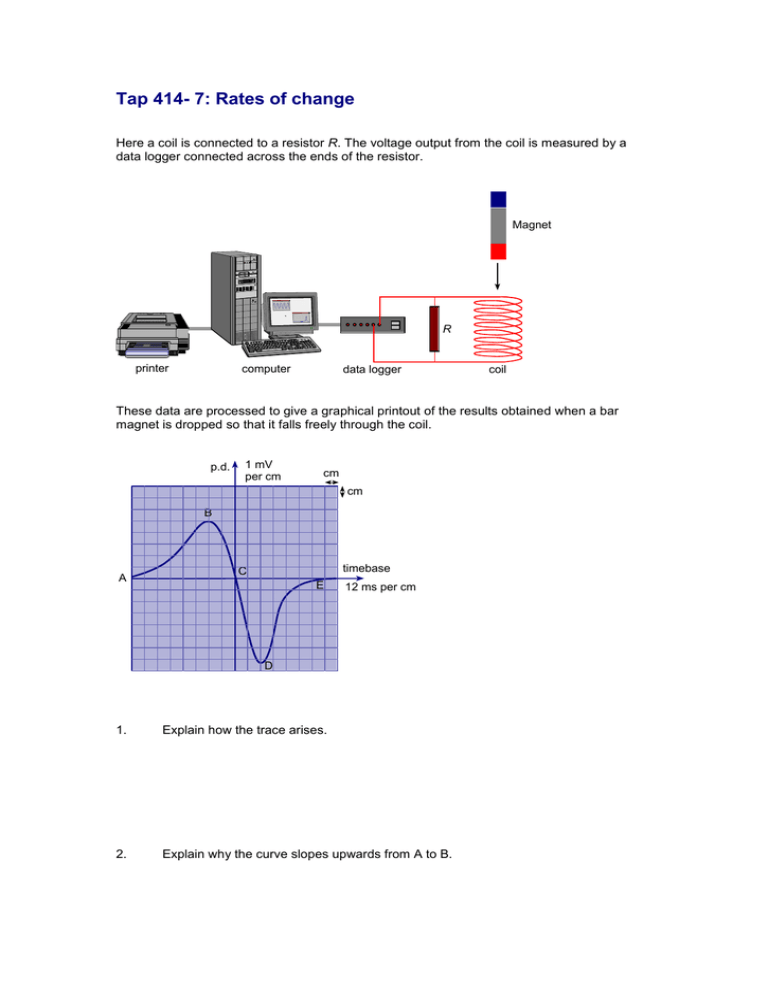
Tap 414- 7: Rates of change Here a coil is connected to a resistor R. The voltage output from the coil is measured by a data logger connected across the ends of the resistor. Magnet Grap h Grap h R printer computer data logger coil These data are processed to give a graphical printout of the results obtained when a bar magnet is dropped so that it falls freely through the coil. p.d. 1 mV per cm cm cm B A timebase C E 12 ms per cm D 1. Explain how the trace arises. 2. Explain why the curve slopes upwards from A to B. 3. Explain why the voltage shown at B has a smaller magnitude than the voltage shown at D. 4. Explain why the graph has a positive and a negative section. 5. The areas under the two segments of the curve are the same. Explain why this is so. The uniform magnetic field inside an MRI scanner has a flux density of 0.40 T. A patient inside the scanner is wearing a wedding ring. A finger movement can rotate the axis of the ring through an angle of 90 as shown in the diagram below: 6. Calculate the average voltage induced in the ring if the ring diameter is 20 mm and the finger movement is completed in a time of 0.30 s. 7. Describe how the ring must move if there is to be no induced voltage. The next questions are about a student’s investigation of the magnetic flux in an iron rod. An iron rod passes through a coil that carries alternating current. probe coil to oscilloscope coil carrying alternating current A detector consisting of a probe coil wrapped around the rod is connected to an oscilloscope that displays the output trace shown in the figure below: Sketch and explain the effect on the oscilloscope trace of each of the following changes. Each change is made separately and starts from the situation shown above. Assume that the voltage and time scales on the oscilloscope remain unchanged. 8. The number of turns on the probe coil is doubled. 9. The probe coil is positioned at the top of the rod. Practical advice These questions relate to an experiment that you may want to demonstrate. A magnet falls freely through a coil, inducing a changing emf in the coil. There are several teaching points: the direction of the emf reverses as the magnet leaves the coil; the acceleration makes the second peak emf higher but the area under the V–t graph (flux) is the same as the magnet enters and leaves. Set the questions at a point when most students will understand all of these effects, and they will be pleased. Answers and worked solutions 1. Flux cuts the coil as the magnet approaches. Flux linkage is constantly changing (due to the non-uniform field of the magnet) so an emf is induced according to Faraday’s law. 2. Increasing speed and stronger field both contribute to the increased rate of change of magnetic flux. 3. The magnet is travelling faster when it leaves the coil so that rate of change of flux is greater. 4. The flux change is in the opposite direction when the magnet leaves the coil compared with when it is entering. 5. The area under the curve represents the total flux change, which is the same leaving as entering. 6. A = r , B = 0.40 T: 2 V dB A dt 0.40 T 1.0 10 2 m 0.3 s 2 0.42 mV. 7. The ring must be moved parallel to the flux lines. 8. The trace height will be doubled because the flux linkage will be doubled and therefore so will the rate of change of flux. 9. The trace height is smaller – the flux is weaker towards the ends. 10. The trace height will be doubled because the rate of change of flux will be doubled and also the horizontal spacing will be halved because the frequency is doubled, i.e. there are twice as many cycles on screen for the same timebase sweep. External references This activity is taken from Advancing Physics chapter 15, 80S


