Soil Moisture Sensors
advertisement
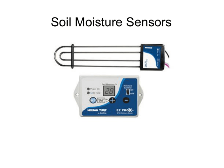
Soil Moisture Sensors Water savings of 46 to 88% reported in Florida compared to systems with rain sensors (Lailhacar et al., 2005) Typical installation – solenoid Locate Valve 3 wires Dry area Atypical installation – controller Connected in controller box Same 3 wires Wiring Moisture sensor Red 0 Controller hot (color wire – yellow, aqua, or other) Moisture sensor Black 0 Valve hot (black) Moisture sensor White 0 Controller common (white) and Valve Common (black) Sensor Location • 4” below ground • Dry representative location – full sun • Avoid driveways and sidewalks • >3’ from sprinkler head • Avoid low areas, bottom of hills • Avoid high foot traffic Install sensor in root zone 1. Install sensor (4-6” deep hole) 2. Valve box for connections 3. Water and allow it to drain – field capacity 4. Set at ~75% of field capacity Why Soil Moisture Sensors Work Soil Classification & Soil Moisture Set at 75% field capacity ~30% field capacity 50 40 Plant available Water 30 PWP & Soil Matrix 20 10 SILTY LOAM SILTY CLAY LOAM SILTY CLAY SILT SANDY LOAM SANDY CLAY LOAM SANDY CLAY SAND LOAMY SAND LOAM CLAY LOAM 0 CLAY Soil Moisture % 60 How many zones? One sensor can be used to control multiple zones Programming the Controller • 1 hr. irrigation • 6 @ 10 min cycles • 6 on/off readings • 0,10,20,30,40,50, or 60 minutes of run time If moisture is adequate then no irrigation Moisture adequate after 1,2,3,4, 5 cycles – remainder of cycles are skipped Data Collection Water Meters 1. Zones without Moisture Sensors vs. 2. Zones with Moisture Sensors Data Collection Datalogger with a Pressure Switch How many irrigation cycles were skipped How much water was saved Record Soil Moisture

