lec09-switches.ppt
advertisement
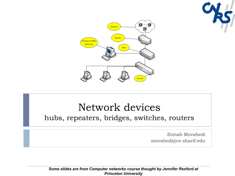
Network devices
hubs, repeaters, bridges, switches, routers
Zeinab Movahedi
movahedi@ce.sharif.edu
Some slides are from Computer networks course thought by Jennifer Rexford at
Princeton University
Outline
Devices that shuttle data at different layers
Switch protocols and mechanisms
2
Repeaters and hubs
Bridges and switches
Routers
Dedicated access and full-duplex transfers
Cut-through switching
Self learning of the switch table
Spanning trees
Virtual LANs (VLANs)
Message, Segment, Packet, and Frame
host
host
HTTP message
HTTP
TCP segment
TCP
router
IP
Ethernet
interface
3
HTTP
IP packet
Ethernet
interface
Ethernet frame
IP
TCP
router
IP packet
SONET
interface
SONET
interface
SONET frame
IP
IP packet
Ethernet
interface
IP
Ethernet
interface
Ethernet frame
Shuttling Data at Different Layers
Different devices switch different things
Network layer: packets (routers)
Link layer: frames (bridges and switches)
Physical layer: electrical signals (repeaters and hubs)
Application gateway
Transport gateway
Router
Bridge, switch
Repeater, hub
4
Frame Packet TCP
header header header
User
data
Physical Layer: Repeaters
Distance limitation in local-area networks
Electrical signal becomes weaker as it travels
Imposes a limit on the length of a LAN
Repeaters join LANs together
Continuously monitors electrical signals on each LAN
Transmits an amplified copy
Repeater
5
Physical Layer: Hubs
Joins multiple input lines electrically
Designed to hold multiple line cards
Do not necessarily amplify the signal
Very similar to repeaters (multi-port repeaters)
Also operates at the physical layer
hub
hub
6
hub
hub
Limitations of Repeaters and Hubs
One large shared link
Each bit is sent everywhere
So, aggregate throughput is limited
E.g., three departments each get 10 Mbps independently
… and then connect via a hub and must share 10 Mbps
Cannot support multiple LAN technologies
Does not buffer or interpret frames
So, can’t interconnect between different rates or formats
E.g., 10 Mbps Ethernet and 100 Mbps Ethernet
Limitations on maximum nodes and distances
7
Shared medium imposes length limits
E.g., cannot go beyond 2500 meters on Ethernet
Bridges
A layer 2 device designed to create two or more LAN
segments, each of which is a separate collision domain.
The purpose is to filter traffic on a LAN, to keep local
traffic local, yet allow connectivity to other segments of
the network.
Filter traffic by looking at the MAC address
Frame filtering
Link Layer: Bridges
Connects two or more LANs at the link layer
Extracts destination address from the frame
Looks up the destination in a table
Forwards the frame to the appropriate LAN segment
Bridges maintain a MAC address table for both segments they are
connected to
If the frame is addressed to a MAC address on the local side of the bridge, it
is not forwarded to the other segment
MAC addresses on the other segment are forwarded
host
host
host
host
host
host
host
host
Bridge
host
host
host
host
9
Link Layer: Switches
Typically connects individual computers
A switch is essentially the same as a bridge
… though typically used to connect hosts, not LANs
Like bridges, support concurrent communication
Host A can talk to C, while B talks to D
B
A
C
switch
10
D
Dedicated Access and Full Duplex
Dedicated access
Full duplex
Host has direct connection to the switch
… rather than a shared LAN connection
Each connection can send in both directions
Host sending to switch, and host receiving from switch
Completely supports concurrent transmissions
11
Each connection is a bidirectional point-to-point link
Bridges/Switches: Traffic Isolation
Switch breaks subnet into LAN segments
Switch filters packets
Frame only forwarded to the necessary segments
Segments can support separate transmissions
switch/bridge
segment
hub
12
segment
segment
hub
hub
Advantages Over Hubs/Repeaters
Only forwards frames as needed
Extends the geographic span of the network
Separate segments allow longer distances
Improves privacy by limiting scope of frames
Filters frames to avoid unnecessary load on segments
Sends frames only to segments that need to see them
Hosts can “snoop” the traffic traversing their segment
… but not all the rest of the traffic
Can join segments using different technologies
13
Disadvantages Over Hubs/Repeaters
Delay in forwarding frames
Need to learn where to forward frames
Bridge/switch must receive and parse the frame
… and perform a look-up to decide where to forward
Storing and forwarding the packet introduces delay
Solution: cut-through switching
Bridge/switch needs to construct a forwarding table
Ideally, without intervention from network administrators
Solution: self-learning
Higher cost
14
More complicated devices that cost more money
Motivation For Cut-Through Switching
Buffering a frame takes time
Suppose L is the length of the frame
And R is the transmission rate of the links
Then, receiving the frame takes L/R time units
Buffering delay can be a high fraction of total delay
Propagation delay is small over short distances
Making buffering delay a large fraction of total
A
15
B
switches
Cut-Through Switching
Start transmitting as soon as possible
Inspect the frame header and do the look-up
If outgoing link is idle, start forwarding the frame
Overlapping transmissions
Transmit the head of the packet via the outgoing link
… while still receiving the tail via the incoming link
A
16
B
switches
Motivation For Self Learning
Switches forward frames selectively
Forward frames only on segments that need them
Switch table
Maps destination MAC address to outgoing interface
Goal: construct the switch table automatically
B
A
C
switch
17
D
Self Learning: Building the Table
When a frame arrives
Inspect the source MAC address
Associate the address with the incoming interface
Store the mapping in the switch table
Use a time-to-live field to eventually forget the mapping
Switch learns
how to reach A.
B
A
18
C
D
Self Learning: Handling Misses
When frame arrives with unfamiliar destination
Forward the frame out all of the interfaces
… except for the one where the frame arrived
Hopefully, this case won’t happen very often
B
A
19
C
D
Switch Filtering/Forwarding
When switch receives a frame:
index switch table using MAC dest address
if entry found for destination
then{
if dest on segment from which frame arrived
then drop the frame
else forward the frame on interface indicated
}
else flood
forward on all but the interface
on which the frame arrived
20
Flooding Can Lead to Loops
Switches sometimes need to broadcast frames
Broadcasting is implemented by flooding
Upon receiving a frame with an unfamiliar destination
Upon receiving a frame sent to the broadcast address
Transmitting frame out every interface
… except the one where the frame arrived
Flooding can lead to forwarding loops
21
E.g., if the network contains a cycle of switches
Either accidentally, or by design for higher reliability
Solution: Spanning Trees
Ensure the topology has no loops
Avoid using some of the links when flooding
… to avoid forming a loop
Spanning tree
22
Sub-graph that covers all vertices but contains no cycles
Links not in the spanning tree do not forward frames
Constructing a Spanning Tree
Need a distributed algorithm
Switches cooperate to build the spanning tree
… and adapt automatically when failures occur
Key ingredients of the algorithm
Switches need to elect a “root”
Each switch identifies if its interface
is on the shortest path from the root
root
And it exclude from the tree if not
Messages (Y, d, X)
23
The switch with the smallest identifier
From node X
Claiming Y is the root
And the distance is d
One hop
Three hops
Steps in Spanning Tree Algorithm
Initially, each switch thinks it is the root
Switches update their view of the root
Switch sends a message out every interface
… identifying itself as the root with distance 0
Example: switch X announces (X, 0, X)
Upon receiving a message, check the root id
If the new id is smaller, start viewing that switch as root
Switches compute their distance from the root
24
Add 1 to the distance received from a neighbor
Identify interfaces not on a shortest path to the root
… and exclude them from the spanning tree
Example From Switch #4’s Viewpoint
Switch #4 thinks it is the root
Then, switch #4 hears from #2
Sends (4, 0, 4) message to 2 and 7
1
Receives (2, 0, 2) message from 2
… and thinks that #2 is the root
And realizes it is just one hop away
3
5
Then, switch #4 hears from #7
25
Receives (2, 1, 7) from 7
And realizes this is a longer path
So, prefers its own one-hop path
And removes 4-7 link from the tree
2
4
7
6
Example From Switch #4’s Viewpoint
Switch #2 hears about switch #1
1
Switch #4 hears from switch #2
Switch 2 hears (1, 1, 3) from 3
Switch 2 starts treating 1 as root
And sends (1, 2, 2) to neighbors
Switch 4 starts treating 1 as root
And sends (1, 3, 4) to neighbors
Switch #4 hears from switch #7
26
3
Switch 4 receives (1, 3, 7) from 7
And realizes this is a longer path
So, prefers its own three-hop path
And removes 4-7 Iink from the tree
5
2
4
7
6
Robust Spanning Tree Algorithm
Algorithm must react to failures
Failure of the root node
Failure of other switches and links
Need to recompute the spanning tree
Root switch continues sending messages
Need to elect a new root, with the next lowest identifier
Periodically reannouncing itself as the root (1, 0, 1)
Other switches continue forwarding messages
Detecting failures through timeout (soft state!)
27
Switch waits to hear from others
Eventually times out and claims to be the root
Evolution Toward Virtual LANs
In the olden days…
Thick cables snaked through cable ducts in buildings
Every computer they passed was plugged in
All people in adjacent offices were put on the same LAN
Independent of whether they belonged together or not
More recently…
28
Hubs and switches changed all that
Every office connected to central wiring closets
Often multiple LANs (k hubs) connected by switches
Flexibility in mapping offices to different LANs
Group users based on organizational structure,
rather than the physical layout of the building.
Why Group by Organizational Structure?
Security
Ethernet is a shared media
Any interface card can be put into “promiscuous” mode
… and get a copy of all of the traffic (e.g., midterm exam)
So, isolating traffic on separate LANs improves security
Load
29
Some LAN segments are more heavily used than others
E.g., researchers running experiments get out of hand
… can saturate their own segment and not the others
Plus, there may be natural locality of communication
E.g., traffic between people in the same research group
People Move, and Roles Change
Organizational changes are frequent
Physical rewiring is a major pain
E.g., faculty office becomes a grad-student office
E.g., graduate student becomes a faculty member
Requires unplugging the cable from one port
… and plugging it into another
… and hoping the cable is long enough to reach
… and hoping you don’t make a mistake
Would like to “rewire” the building in software
30
The resulting concept is a Virtual LAN (VLAN)
Example: Two Virtual LANs
RO
R
31
RO
RO
O
Red VLAN and Orange VLAN
Bridges forward traffic as needed
Example: Two Virtual LANs
R
O
O
R
O
O
R
R
O
RO
O
R
R
O
R
O
R
32
Red VLAN and Orange VLAN
Switches forward traffic as needed
Making VLANs Work
Bridges/switches need configuration tables
Saying which VLANs are accessible via which interfaces
Approaches to mapping to VLANs
Each interface has a VLAN color
Each MAC address has a VLAN color
Only works if all hosts on same segment belong to same VLAN
Useful when hosts on same segment belong to different VLANs
Useful when hosts move from one physical location to another
Changing the Ethernet header
33
Adding a field for a VLAN tag
Implemented on the bridges/switches
… but can still interoperate with old Ethernet cards
Moving From Switches to Routers
Advantages of switches over routers
Plug-and-play
Fast filtering and forwarding of frames
No pronunciation ambiguity (e.g., “rooter” vs. “rowter”)
Disadvantages of switches over routers
34
Topology is restricted to a spanning tree
Large networks require large ARP tables
Broadcast storms can cause the network to collapse
Comparing Hubs, Switches, Routers
Hub/
Bridge/
Router
Repeater Switch
Traffic isolation
no
yes
yes
Plug and Play
yes
yes
no
Efficient routing
no
no
yes
Cut through
yes
yes
no
35
Conclusion
Shuttling data from one link to another
Bits, frames, packets, …
Repeaters/hubs, bridges/switches, routers, …
Key ideas in switches
36
Cut-through switching
Self learning of the switch table
Spanning trees
Virtual LANs (VLANs)
