Presentation Slides)
advertisement
SFF
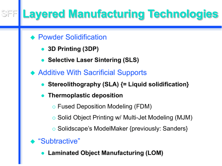
Layered Manufacturing Technologies
Powder Solidification
3D Printing (3DP)
Selective Laser Sintering (SLS)
Additive With Sacrificial Supports
Stereolithography (SLA) {= Liquid solidification}
Thermoplastic deposition
Fused Deposition Modeling (FDM)
Solid Object Printing w/ Multi-Jet Modeling (MJM)
Solidscape’s ModelMaker {previously: Sanders}
“Subtractive”
Laminated Object Manufacturing (LOM)
SFF
Layered Solidification Processes
Liquid-Based Approaches
Stereolithography
(latest process needs almost no “supports”)
Powder-Bed Based Approaches
3D
Printing (Z-Corporation)
Selective
Laser Sintering
SFF
Stereolithography (SLA)
First commercial layered
manufacturing technology (1988)
Photo-curable liquid resin
www.3dsystems.com
SFF
Stereolithography (SLA)
UV laser beam solidifies the top layer
of a photosensitive liquid.
UV Laser Beam
Photopolymer
Build Stage
SFF
Stereolithography: Apparatus
SFF
Stereolithography
Pre-process:
Orient
part.
Choose
Slice
slice thickness.
parts and plan supports.
SFF
Stereolithography
Process:
Position
build platform (stage)
just below liquid resin surface.
Smooth
surface with re-coater blade.
Scan
the outline of the current slice,
loosely hatch part interior with laser.
Lower
the build platform for next layer.
SFF
Stereolithography
Post-process:
Raise
part and drain out liquid.
(except liquid trapped by loose hatch)
Break
off supports.
Rinse
in isopropanol and water.
Dry
with air hose.
Post-cure
(strengthen) in UV oven.
SFF
Stereolithography
Characteristics:
Slow process
Supports must be removed by hand
Lab environment necessary (gasses!)
Needs trained operator
Laser lasts 2000hrs, costs $20’000!
Little material choice, ($700 per gallon)
Parts can be brittle, fragile
SFF
Stereolithography
Characteristics (cont.):
High accuracy
Layer thickness 0.001 - 0.006”
Minimum feature size 0.003 - 0.012”
Large build volume
Up to 20 x 20 x 23”
SFF
Powder-based Approaches
Key Properties:
Needs
no supports that must be removed!
Uniform
This
bed of powder acts as support.
powder gets selectively (locally)
glued (or fused) together to create the
solid portions of the desired part.
SFF
3D Printing -- Principle
Selectively deposit binder droplets onto a
bed of powder to form locally solid parts.
Head
Powder Spreading
Printing
Powder
Feeder
Build
SFF
3D Printing: Some Key Players
Z Corporation: http://www.zcorp.com/
Plaster and starch powders
for visualization models.
Soligen: http://www.zcorp.com/
Metal and ceramic powders
for operational prototypes.
ProMetal: http://www.prometal-rt.com/
Metal sintering process
for operational prototypes and art work.
Therics Inc.: http://www.therics.com/
Biopharmaceutical products,
tissue engineering.
SFF
3D Printing: Z Corporation
The Z402 3D Printer
Speed: 1-2 vertical inches per hour
Build Volume: 8" x 10" x 8"
Thickness: 3 to 10 mils, selectable
SFF
3D Printing: Z Corporation
SFF
3D Printing: Z Corporation
Digging
out
SFF
Optional Curing: 30 min. @ 200ºF
Keep some powder in place
<-- Tray for
transport
SFF
3D Printing: Z Corporation
Cleaning up in the de-powdering station
SFF
3D Printing: Z Corporation
The finished part
Zcorp,
6"
6
diam.,
hrs.
SFF
120 Cell -- Close-up
SFF
Parallel Projection of the 4D 120-Cell
Zcorp,
6"
6
diam.,
hrs.
SFF
Morin Surface
3D-Print
6" diam.
5 hrs.
This is the half-way point of a sphere eversion
(without causing creases or tears).
SFF
3D Color Printing: Z Corporation
The Z402C 3D Color Printer
Differences compared to mono-color printer:
Color print head with: Cyan, Yellow, Magenta,
Black, and Neutral.
Smaller build area.
Specs:
Speed: 0.33 - 0.66 vertical inches per hour
Build Volume: 6" x 6" x 6"
Layer Thickness: 3 to 10 mils, selectable
Color depth: 80 mils below surface
SFF
3D Color Printing: Z Corporation
SFF
3D Color Printing: Z Corporation
Use compressed
air to blow out
central hollow
space.
SFF
3D Color Printing: Z Corporation
Infiltrate Alkyl Cyanoacrylane Ester = “super-glue”
to harden parts and to intensify colors.
SFF
3D Color Printing: Z Corporation
“Lizard-Frame”: Final Infiltrated Part
SFF
Hypercube, Perspective Projections
SFF
Two Ways to Make a Hypercube
3D Color Print
Assembly of
flat FDM parts ==>
SFF
What Can Go Wrong ?
-- Parts may brake before infiltration
SFF
What Else Can Go Wrong ?
Blocked glue lines
Crumbling parts
SFF
What Else Can Go Wrong ?
Some blocked glue lines
Uneven coloring Art ?
SFF
Post-Processing for 3D-Printing
Surface is porous, dusty.
Seal and strengthen the part:
Dip
in wax:
Nice smooth finish
Needs separate waxing station
Infiltrate
with “superglue”:
Tedious, dirty manual labor
Spray-paint
with a sealant:
Polyurethane (yellowish, smelly)
Krylon (invisible)
SFF
Post-Processing for 3D-Printing
Spray-paint
surface with Krylon
SFF
3D Printing: Z Corporation
An Informal Evaluation
Fast
!
Running
expenses: moderate,
(but overpriced powder)
Color
print head and tubes need
some care in maintenance.
Somewhat
Lot’s
messy cleanup !
of dust everywhere ...
SFF
Selective Laser Sintering (SLS)
Key Points:
Powder
gets solidified with a laser.
Powder
is kept just below melting point,
heat from laser will fuse powder grains.
Un-fused
powder acts as support,
can easily be removed later.
Many
different materials can be used
when mixed with a suitable binder:
nylon, metal, ceramics …
SFF
SLS: Conceptual View
SFF
SLS Players
3D SYSTEMS
Representing the fourth generation of SLS®
(selective laser sintering) technology,
Vanguard™ and Vanguard™ HS (High Speed),
are the first SLS® systems developed specifically
for advanced manufacturing applications.
With the Vanguard system you can move directly
from a CAD file to a durable, functional plastic or
metal part or tool — in a fraction of the time
required for traditional machining and tooling.
http://www.3dsystems.com/products/sls/vanguard/index.asp
SFF
SLS from 3D SYSTEMS
Use
•
•
•
•
•
Vanguard or Vanguard HS system for:
Plastic or metal parts, patterns & prototypes
Complex metal tooling inserts
Highly Durable Parts
Parts with small features
Short runs of plastic & metal parts
Benefits:
• High part accuracy
• Fast build speed
• Unattended operation
• Uses plastic or metal materials
• Respond to customer demands
• Worldwide service and support
SFF
SLS: Laserform Parts
SFF
The Most Challenging SFF Part
3rd-order 3D Hilbert Curve:
much weight
much length
no supports
only two tubeconnections
between the
two halves.
SFF
Fabricated by ProMetal
SFF
ProMetal Process
A
‘green’ part is first formed,
composed of stainless steel powder
and a selectively applied binder.
This
part is built bottom-up, layer-by-layer
under direct computer control.
This
green part is then sintered,
the binder is drained out
and replaced by liquid bronze.
ProMetal
is a division of
‘The Ex One Company’, Irwin, PA.
SFF
The Objet PolyJet Process
SFF
The Objet PolyJet Process
Pointer to the company:
http://www.2objet.com/
See the movie ...
http://www.youtube.com/watch?v=oMQWGBgNCtg
SFF
Which Process Should You Pick?
Do you need a prototype (not just a model)?
SLS, FDM (for robustness, strength).
Do you need a mold for a small batch?
SLA (for smooth, hard surface).
Does part need multiple colors?
3D Color-Printing.
Does part have convoluted internal spaces?
3D-Print, SLS, SLA (easy support removal).
SFF
Informal Process Ratings Matrix
Hollow
Hollow
2 Nested,
Sphere Sphere with Perforated
Drain/Vent Spheres
3D
Hilbert
Pipe
Preassembled
Gear
Mechanism
LOM
(F)
F
F
D
F
SLA
FDM
3D-P
SLS
(F)
(F)
(F)
(F)
A
F
A
A
B
C
A
A
B
C
C
B
C
D
B
B
