Prof. Dooley's Notes
advertisement

POLYMER RHEOLOGY - BASIC EQUATIONS
AND FLOW BEHAVIOR
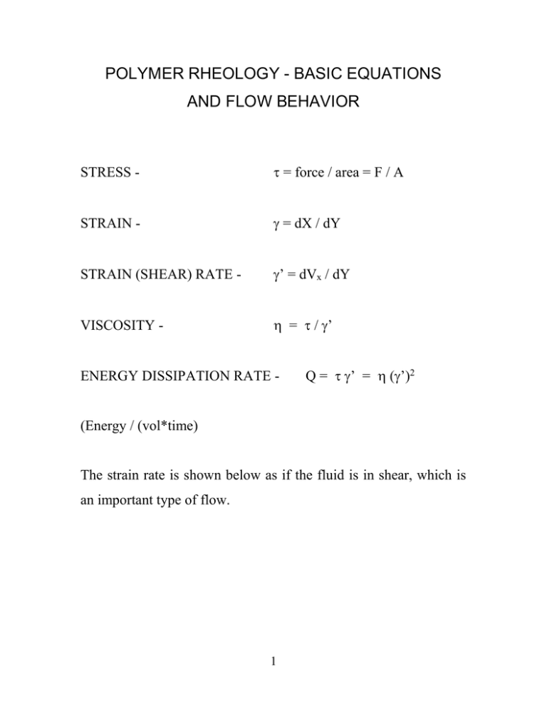
STRESS -
= force / area = F / A
STRAIN -
= dX / dY
STRAIN (SHEAR) RATE -
’ = dVx / dY
VISCOSITY -
= / ’
ENERGY DISSIPATION RATE -
Q = ’ = (’)2
(Energy / (vol*time)
The strain rate is shown below as if the fluid is in shear, which is
an important type of flow.
1
Y
DX
X
F
Vx + dX
DY
A
Why is rheological behavior of polymer melts and solutions
important?
(a) Can relate to M;
(b) Can relate to thermo. properties such as volumetric
behavior;
but most important:
(c)
Must understand in order to process polymer melts,
solutions.
2
Typical ’ in processing:
compression molding -
1-10 s-1
calendering
-
10-102 s-1
extrusion
-
102 -103 s-1
injection molding
-
103 -104 s-1
100 and above usually
out of Newtonian range
From processing view, the main classes are:
Thermoplastic:
the resin is heated to make a viscous liquid and then
processed into a usable object without much additional chemistry.
Example:
polyethylene, polystyrene.
Thermoset: upon heating, further reaction occurs to make molecules “set up”
into a useful product. Chemistry occurs, so these are sometimes called “reactive
polymers”. The resin may be provided as either small molecules or “prepregs”—
partially polymerized stuff.
Example:
polyurethanes, phenol-formaldehyde,
melamine-formaldehyde, epoxy glue. Usually processed in prepreg form.
Some key phenomena in non-Newtonian rheology seen at:
http://web.mit.edu/nnf/research/phenomena/Demos.pdf
http://web.mit.edu/nnf/
http://www.youtube.com/watch?v=5GWhOLorDtw (ultimate cornstarch expt.)
3
COMPRESSION MOLDING
Platen
Heat
and
Cooling
Mold
Plunger
Guide
Pins
Heat
and
Cooling
Mold
Cavity
Compound to be molded
Platen
Hydraulic
Pressure
Hydraulic
Plunger
4
FOUR-ROLL CALENDAR
Wad of plastic
To conditioning
equipment
EXTRUDER – CYLINDRICAL DIE
Heat
Feed
hopper
cooling
water
Drive shaft
Screw
5
INJECTION MOLDER
Nozzle
Hydraulic
Pressure
Stages of Injection Molding - (1) Retract and refill; (2) Soak (usually
longest t; (3) Shot; (4) Hold t; (5) Gate freezes; (6) Piston retracts;
(7) Ejection
Typical Problems - (1) Weld lines (where 2 melting fronts meet);
(2) Warpage (due to elastic stresses); (3) Incomplete freezing.
6
The mold entrance (sprue) is at top.
7
BEHAVIOR– MELTS AND CONCENTRATED SOLUTIONS
Almost everything is really a fluid, see:
http://www.research-equipment.com/viscosity%20chart.html
http://www.smp.uq.edu.au/pitch/
7
10
High MW
Log
0
Low MW
2
10
104
-4
10
Log ’
Materials with broad MWD relax at lower ',
and relaxation region is broader.
Short branches with L < entanglement L leads to behavior similar to
linear polymers (e.g., LLDPE)
May not reach high shear plateau () prior to shear-induced chain
degradation (e.g., red blood cells).
Shear thinning (pseudoplastic) behavior results from rotation of
polymer coils on shearing. Low shear – entangle/disentangle coils.
High shear – too fast to entangle. So /’ decreases. Some energy
stored elastically – coils can elongate.
8
Y-axis is:
C1 + log()
of the melt;
X=axis is:
C2 + log(M)
Zero-shear scales with M. The transition is the entanglement M.
Power is 1.7 below transition, 3.4 above { = K [M]3.4 }. Entanglement
transition also seen in solutions (below).
9
Y-axis is sp, X-axis is c (g/dL). Below entanglement transition polymers
show less elastic behavior, wider Newtonian range, less “extra” stress
(stored energy) upon shearing.
10
Elasticity is an important characteristic of polymer flows - observed as:
(1)
Die Swell - polymer exits a die; stored (elastic) energy released
perpendicular and parallel to flow.
(2)
In molding, too much “strain hardening” undesirable, because the
material often relaxes slowly, causing warpage of final product. Especially true
of thermosets and thermoplastics with high MW tails.
(2) Rod Climbing - Newtonian fluid in rotation forms a vortex; a polymer will
climb the shaft.
(4)
Transient Effects on Fluid Behavior - On acceleration, polymer may be
viscous at short relaxation times, become viscoelastic at medium relaxation
times / higher ', then become elastic (low strain) at high shear rates or long
relaxation times. At elastic conditions, deformation in phase with applied stress.
In graph, consider strain rate as control parameter – can’t have high strain with
Hookean solid; can’t have low strain with Newtonian fluid.
E.G.
Purely
Viscous
–
corn
starch/water
Nonlinear
Viscoelastic
Newtonian
Strain
Finite Elastic
slowly
Shear (strain) rate * characteristic relax. time
11
poke
your finger in it
(low
Hookean
–
deform.
’)
to
What factors determine the characteristic relaxation time?
Measure of elasticity – 1st Normal Shear Stress Coefficient
12 = (11 - 22) / (’)2
Where 1 = principal flow direction; 2 = perpendicular to flow.
For many polymer melts, 12 function similar in behavior to .
(5) Behavior in creep (constant stress) or stress relaxation (constant strain)
experiments.
Idealized:
1 d
E dt M
d
dt
(Maxell model, viscous and elastic elements in series so the strains sum)
y
Liquid in shear
x
F=k’x = k x/x
x
x
12
Solid in extension
Newton
Hooke
These two equations represent viscous liquids (in shear or extension) and
elastic solids (in extension).
Remember that σ (or τ, as sometimes
symbolized) = F/A so the 1st is also a force equation. Also remember that γ’
(or ) is a deformation rate:
= x/y
[Strain]
so…
(1 / y )(
d x
) [Strain Rate or Shear Rate]
dt
Then sum the strains of the two
(viscous and elastic) elements –
arrange in series – to get the
Maxwell eq.
13
or
(ideal)
or
2
(real)
Permanent
1/E
Set
1
time
Response of a Maxwell fluid (ideal) and real polymer fluid to a
creep test - profile shown in red. Note: elastic recovery should
equal initial strain.
A good simple discussion of these points can be found at:
http://www.vilastic.com/
(see tech. notes on “A Structural View of Rheology” and
“Rheological Parameters for Viscoelastic Materials”.
14
ELONGATIONAL FLOWS
e.g. – fiber spinning, fiber drawing, film blowing.
Draw ratio = take - up rate/extrusion rate –
- Typically 10-100
- Get uniaxial orientation.
MELT SPINNING
15
FIBER DRAWING
Fiber shapes: (a) cylindrical; (b) quadrilobal (gives less packing density).
- lower T to lock in orientation
- flow not rotational as in shear – no perpendicular variation in
- Wet spinning – spin into bath to cause coagulation (e.g., rayon)
- Dry spinning – spin into gas
16
FILM BLOWING
Blow up ratio – bubble D/die D = ~1.5 – 4
- Get biaxial orientation
- Want to control “frost line” for semi-crystalline materials
17
Strain hardening and
structure development
3 0
Strain hardening
Strain rate = ’
= dVz/dZ
This is a generic curve – dilution with solvent stretches it to right.
The 2nd part of the curve (strain hardening) can be simulated fairly simply
with a “dumbbell” model of the chain:
http://demonstrations.wolfram.com/RheologicalBehaviorOfFENEDumbb
ellSuspensionUnderElongational/
An elongational flow is one where ’ = dVz/dz is THE important
deformation. The ratio between the stress zz and this shear rate is the
elongational viscosity, e.
e = (zz yy) / ’
(why are both stresses important?)
18
Constant strain rate requires exponential increase in fluid
velocity –
d = L / L
d/dt = ’ = (1/L) (L/t)
So if ’ = constant, then:
Ln(L/L0) = ’ t
De = Deborah number = charac. relaxation t / charac. exp. t
texp might be a residence t
trelax might be obtained in a creep or strain recovery test
As De , “elastic” component of fluid usually
19
Elastic stresses in contracting/expanding flows
7.7/1 contraction.
Vortexes, instabilities result from elastic
(normal) stresses and “slip” (2 adjacent layers not at same at the
boundary).
20
Rheology – The Purely Viscous
(Generalized Newtonian) Fluid
All materials deform if a high enough force (F), or stress (F/A,
abbreviated or ), is applied. The normal response to is change in
momentum. For 3-D flow, when a small element of fluid enters a V, it
may, in addition to experiencing the same F, experience a new F causing a
change in direction of its momentum. In other words, momentum in the zdirection can become momentum in the x-direction. A simple example is
fluid above a moving plate, impinging on a second plate. It is flowing in
shear (x-direction) until it hits the plate. The primary is the shear exerted
by its confining walls (see Fig. 1, Rheo1). The second plate exerts a new F,
causing a change in momentum perpendicular to the moving plate. It seems
like a simple process to analyze.
For almost all polymeric fluids, this process would be impossible to
analyze analytically, and would even be difficult to describe numerically,
even given the fastest possible computer. Three reasons:
(1) Equations relating to or ’ for polymer fluids are not known exactly.
(2) The change in direction of momentum leads to PDEs which are highly
nonlinear.
21
(3) The flow at the plate may be turbulent (3-D), and it is hard to describe 3D turbulence even in simple Newtonian fluids.
Therefore we usually try to describe polymer flows in a way in which
it does not become necessary to account for changes in momentum – i.e.,
flows in which the principal flow is in a single direction. In such a case the
3-D Newton’s Laws in the 3 coordinate directions (usually known as the
Stress Equations of Motion) usually become:
M1/t = 11 Δ(area-1) + 21 Δ(area-2) + 31 Δ(area-3) + m g1
Δarea-1 = Δ(length-2) Δ(length-3) , etc. (the area of the face perpendicular
to the 1-direction; this is the area the force is acting on); M = momentum, m
= mass.
1
3
2
3
(area)2 on top, bottom; (area)3 on front, back sides
This is written for momentum in the 1-direction; momentum in the other two
directions give similar equations, 3 in all. This equation says:
change in momentum with time = sum of forces on fluid volume
22
one on each face (area) plus gravity (gravity exists in one direction)
one stress acts in the 1-direction on fluid flowing in the 1-direction [e.g.,
pressure, which acts equally in the 1,2, and 3 directions, on the 1, 2, and
3 (respectively) faces (areas) of the fluid]. This is called a normal stress.
Other 2 stresses are shear stresses of the type discussed previously.
Dividing by Δ(volume):
(V1)/∂t = 11 /x1 + 21 /x2 + 31 /x3 + g1
(similar equations for 2 and 3 directions)
The normal stresses (e.g., 11 ) split into pressure and non-pressure terms.
Leads to:
(V1)/t = - p / x1 + 11 /x1 + 21 /x2 + 31 /x3 + g1
(pressure term is negative – by convention a force on a fluid in the +
direction is positive)
The eqs. look complex in other coordinate systems (cylindrical, spherical),
but basic idea is the same.
Any book on polymer rheology or fluid
mechanics gives eqs. for the common coordinate systems.
23
Note: 12
=
21
ETC. – if not, the (micro) fluid volume element would
rotate.
FORM OF STRESS – DEFORMATION RELATIONSHIPS
For materials we think of as “liquid”, both the normal and the shear stresses
are functions of the relevant shear rates, T and P (at least, but P dependence
usually small) :
21 = F{V1/x2 ; V2/x1 ; T ; P}
Newtonian fluid:
21 = η{T ; P} (2) [(1/2) (V1/x2 + V2/x1 )]
← This [
called the d12 deformation
Purely Viscous (Generalized Newtonian) Fluid:
21 = η {T ; P; shear rates} (2) (d12)
24
] is
Since a factor of ½ is usually introduced to all deformations. The
purely viscous model can be written in matrix form as:
= 2 D ; note that 2 D =
v (v) T
We can define a similar quantity related to rotation of the fluid, the
vorticity tensor: 2 =
v (v) T
For flows with no micro rotation, the deformation tensor is
symmetric.
Power-Law Fluid (most commonly used Purely Viscous model):
21 = η {T ; P; ∑ ∑ (dij)2} {V1/x2 + V2/x1 }
i j
Why? - Already know η ↓ as γ’ ↑; as fluid disentangles
- Any deformation of fluid should lead to less entanglement
- Why not all deformations acting equally on η?
- What type of deformation presents a problem here?
25
Exact form of η:
η = m [ ½ ∑ ∑ (dij)2 ] (n-1)/2
m = modulus of viscosity – has same units as if n = 1
n = power law index (~0.2-0.8 for most melts and concentrated solutions)
NOTE: In all examples below, we can relate the term in brackets to ’
simply [usually ’2 ] . So as ’ .
26
Power-law is just one type of viscosity model (“constitutive equation”).
Some others shown above.
27
Typical power-law fluid behavior. “Consistency” is another name for m
(also called “modulus of viscosity”). Plot on log-scale, get straight lines.
28
For a purely shear flow, Power-Law model predicts a zero ψ12, so it’s no
good for modeling any “elastic” phenomenon.
This also means it
underpredicts the power requirement (pressure drop, pump speed, etc.) for
any flow. As γ’ ↑, it gets better. Why?
29
E.G. 1 – FLOW THROUGH SLIT DIE
X=L
X
X
Y=H
Z
Z = W0
Can prove that Vy = Vz = 0 as long as flow not turbulent. For most polymer
flows, turbulence is not a problem – they are laminar.
The proofs for Vy and Vz are subtle, but follow from fact that X is the only
direction of macroscopic flow (flow you could see with the naked eye).
This means:
→ ∂Vx/ ∂y = γ’ ≠ 0 (otherwise, Vx = 0, since it’s 0 at wall)
30
→ ∂Vy/ ∂x = 0 (since Vy = 0)
→ dyx = γ’
→ τyx = η{T ; P} γ’
[Newtonian]
→ τyx = m (γ’)n = η{T ; P ; γ’} γ’
[Power-Law]
NOTE: A Newtonian Fluid can be thought of as a special case of
the power-law fluid, for n = 1.
So if we substitute all this into the stress equations, only one equation
survives, the x-direction. Finally, assuming steady flow (no time derivative)
and no (or negligible) gravity, we get:
+ ∂p /∂ x = + ∂yx /∂y
We already know that the yx is only a function of y (the Shear Force
only depends on how close we are to the shear surfaces, which in this
case are the walls at y = 0 and y = H)
31
The pressure only varies with x (pressure drives flow in x-direction, since
no moving surfaces). So we have:
F(x) = F(y)
There is only one way it can be true – if both F(x) and F(y) are constants.
This means P varies linearly with x (parallel to flow), and shear stress yx
varies linearly with y (perpendicular to flow). Or (forgetting about boundary
conditions):
yx = (ΔP/ΔX) (some linear function of y)
The linear function of y is always maximum at the wall (why?) and zero at
the centerline of the y-dimension (in this case, H/2). This is also a general
result for pressure-driven shear flows.
Finally, substitute the fluid model (Newtonian, Power-Law, or whatever) in
the above equation to get an equation that involves ∂Vx/ ∂y = γ’ and y as
variables.
Integrating this gives the velocity as a function of y≥2 and
(ΔP/ΔX)1/n, and whatever parameters appear in the fluid model.
Integrating velocity once again, and multiplying by the cross sectional area,
to get average flow rate Q, gives a function of y≥3. Exact solutions are in
any standard text. So to summarize, for this steady laminar shearing flow
(SLSF):
32
- yx proportional to (ΔP/ΔX); shear rate proportional to (ΔP/ΔX)(1/n)
- yx proportional to direction perpendicular to flow to first power;
shear rate proportional to this direction to 1/n power.
- Flow rate (Q) proportional to (ΔP/ΔX)1/n and the perpendicular
direction to the ≥3 power
- the flow rate (Q) is inversely proportional to the viscosity
These results are amazingly correct for any pressure-driven SLSF through
almost any kind of shape, no matter how complex.
E.G. 2 – FLOW THROUGH CYLINDRICAL DIE
This is the process studied in the extruder demo. For a cylindrical die,
the direction of flow is Z, the direction perpendicular to flow (over which τ,
γ’, and Vz change) is r. The exact results for the power-law fluid are:
rz = (ΔP/L) (r/2)
Note substitution of (ΔP/L) for (ΔP/ΔZ) (total pressure drop per total length)
- ∂Vz/ ∂r = γ’ = [(ΔP/L) (r / 2m)]1/n
33
Q = volumetric flow rate = [(n π R3)/(1 + 3n)] [(ΔP/L) (R / 2m)]1/n
So Q = (γ’ at wall) [(n π R3)/(1 + 3n)]
η = m (γ’ at wall)n-1
These eqs. implemented in EXTRUDE2.XLS. Note that they are also the
basic equations of a capillary rheometer, except the way we get ΔP is
different. How?
34
E.G. 3 – DRAG FLOW
A “drag flow” means that one surface is moving. The moving surface
drives the flow, so no P necessary – in fact, if we implement a drag flow in
a closed or almost closed space, P will increase, and this is the basis for
many pumps (gear pumps, extruders, etc.). In other words, energy input
from a moving surface has to either drive flow, increase P, or some
combination.
Moving surface at U velocity
Vx
H
y
x
L
Note: z is - Vx, Vy, Vz functions of y only, except at y-walls. The
continuity eq. (mass balance) requires this V-profile.
Continuity: 0
V y
y
35
x-momentum: 0
P
x
y-momentum: 0
P
y
z-momentum: 0
P
z
yx
y
yz
y
So continuity gives Vy = constant = 0 ; y-momentum gives P independent of
y, z-momentum gives:
P = A z + g(x) . Substitute this into the x-
momentum eq.:
g’(x) = constant = B ; g = B x + P0 ; P = A z + B x + P0
But since z is , then A must = 0, leaving:
B
yx
y
Or: yx = B y + C
Thinking about the process, it is obvious that the maximum force (or ) will
be at the moving surface (y = H). So we know B is positive. From what we
know about power-law fluids, this means minimum η will be at this same
surface. Since Q α (1/η), this means that a power-law fluid will have Q ↓
rapidly as we move perpendicularly from the moving surface – the
dependence is much greater than for a Newtonian fluid. This means that
36
when you pump polymers, the maximum perpendicular distance (sometimes
called the “clearance”) must be smaller than for Newtonian fluids.
[e.g., look at extruder screw designs]
For a Newtonian Fluid in “perfect” (no clearance) drag flow, the P/x is
given by:
P/x = 6 U / H2
This shows why it’s possible to generate very high P’s in an extruder (long
X), but not in a gear pump unless the clearance between the gears (H) is very
small.
The problem (Newtonian or Power-Law) is solved by substituting the
constitutive eq. into yx = B y + C, then integrating twice, with B.C.’s??
The other SLSF results for power-law hold!
Complex Flow Phenomena in Molding
Flows in molding complicated by: (a) T-distribution in mold; (b) effects of
fillers on rheology (more stiff); (c) wall slip (which is a good thing here); (d)
difficulties in filling crevices.
37
vs. 21 SBR /
carbon
black
Velocity
into mold
vs. 21
The heavily “filled” system is essentially Bingham. The slip makes mold
filling easier.
38
Gate P
vs. t
The higher shear stresses result in more heat dissipation, leading to greater
rates of cure.
39
40


