F601 Meanings of the symbols used on the device
advertisement
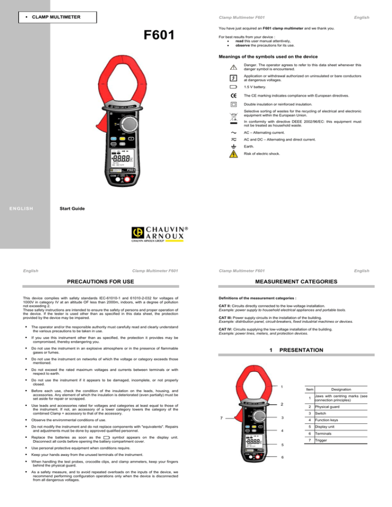
CLAMP MULTIMETER Clamp Multimeter F601 F601 English You have just acquired an F601 clamp multimeter and we thank you. For best results from your device : read this user manual attentively, observe the precautions for its use. Meanings of the symbols used on the device Danger. The operator agrees to refer to this data sheet whenever this danger symbol is encountered. Application or withdrawal authorized on uninsulated or bare conductors at dangerous voltages. 1.5 V battery. The CE marking indicates compliance with European directives. Double insulation or reinforced insulation. Selective sorting of wastes for the recycling of electrical and electronic equipment within the European Union. In conformity with directive DEEE 2002/96/EC: this equipment must not be treated as household waste. AC – Alternating current. AC and DC – Alternating and direct current. Earth. Risk of electric shock. E N G LI SH Start Guide English Clamp Multimeter F601 Clamp Multimeter F601 PRECAUTIONS FOR USE This device complies with safety standards IEC-61010-1 and 61010-2-032 for voltages of 1000V in category IV at an altitude OF less than 2000m, indoors, with a degree of pollution not exceeding 2. These safety instructions are intended to ensure the safety of persons and proper operation of the device. If the tester is used other than as specified in this data sheet, the protection provided by the device may be impaired. The operator and/or the responsible authority must carefully read and clearly understand the various precautions to be taken in use. If you use this instrument other than as specified, the protection it provides may be compromised, thereby endangering you. Do not use the instrument in an explosive atmosphere or in the presence of flammable gases or fumes. Do not use the instrument on networks of which the voltage or category exceeds those mentioned. Do not exceed the rated maximum voltages and currents between terminals or with respect to earth. Do not use the instrument if it appears to be damaged, incomplete, or not properly closed. Before each use, check the condition of the insulation on the leads, housing, and accessories. Any element of which the insulation is deteriorated (even partially) must be set aside for repair or scrapped. MEASUREMENT CATEGORIES Definitions of the measurement categories : CAT II: Circuits directly connected to the low-voltage installation. Example: power supply to household electrical appliances and portable tools. CAT III: Power supply circuits in the installation of the building. Example: distribution panel, circuit-breakers, fixed industrial machines or devices. CAT IV: Circuits supplying the low-voltage installation of the building. Example: power lines, meters, and protection devices. 1 Observe the environmental conditions of use. Do not modify the instrument and do not replace components with "equivalents". Repairs and adjustments must be done by approved qualified personnel. Replace the batteries as soon as the symbol appears on the display unit. Disconnect all cords before opening the battery compartment cover. Use personal protective equipment when conditions require. Keep your hands away from the unused terminals of the instrument. When handling the test probes, crocodile clips, and clamp ammeters, keep your fingers behind the physical guard. As a safety measure, and to avoid repeated overloads on the inputs of the device, we recommend performing configuration operations only when the device is disconnected from all dangerous voltages. PRESENTATION 1 2 Use leads and accessories rated for voltages and categories at least equal to those of the instrument. If not, an accessory of a lower category lowers the category of the combined Clamp + accessory to that of the accessory. English 7 3 4 5 6 Item Designation 1 Jaws with centring marks (see connection principles) 2 Physical guard 3 Switch 4 Function keys 5 Display unit 6 Terminals 7 Trigger English 1.1 Clamp Multimeter F601 Clamp Multimeter F601 THE ROTARY SWITCH 1.3 The rotary switch has five positions. To access the , , , , functions, set the rotary switch to the desired function. Each setting is confirmed by an audible signal. The functions are described in the table below ; 5 Item 4 1 OFF mode – Switches the clamp multimeter off 2 AC, DC voltage measurement (V) 3 3 2 Function English THE DISPLAY UNIT 5 6 Item 1 2 Continuity test 3 Resistance measurement Ω 4 Diode test 1 1.2 4 AC current measurement (A) 5 Temperature measurement (°C/°F) Function 1 Display of the modes selected (keys) 2 Display of the measurement value and unit 3 Display of the MAX/MIN modes 4 Type of measurement (AC or DC) 5 Display of the selected modes (switch) 6 Spent battery indication 5 THE KEYS OF THE KEYPAD 1 2 1.3.1 3 Item 1 Storage of values, disabling of display Compensation of the resistance of the leads in the continuity and ohmmeter function 4 5 2 Selection of the type of measurement (AC, DC) 3 Activation or de-activation of the backlighting of the display unit 4 Activation or de-activation of the MAX/MIN mode Activation or de-activation of the INRUSH mode in A 5 The symbols of the display unit Function Clamp Multimeter F601 Designation AC Alternating current or voltage DC Direct voltage Storage of the values and hold of the display Frequency measurements (Hz) English Symbol Max Maximum RMS value Min Minimum RMS value V Volt Hz Hertz A Ampere Ω Ohm m Milli- prefix k Kilo- prefix Clamp Multimeter F601 English 2 Compensation of the resistance of the leads USE Continuity test 2.1 Diode test Permanent display (automatic switching off deactivated) Spent batteries indicator 1. 2. The O.L (Over Load) symbol is displayed when the display capacity is exceeded. 1.4 COMMISSIONING Insert the batteries supplied with the device as follows: 3. Using a screwdriver, unscrew the screw of the battery compartment cover (item 1) on the back of the housing and open it. Place the 4 batteries in the compartment (item 2), taking care to get the polarities right. Close the battery compartment cover and screw it to the housing. THE TERMINALS The terminals are used as follows: Item Cold terminal (COM) 2 Hot terminal (+) 2 11 2 692879A02_Ed1_01/2012 1 Function 1
