Functional and Molecular Imaging for Radiation Therapy Guidance
advertisement

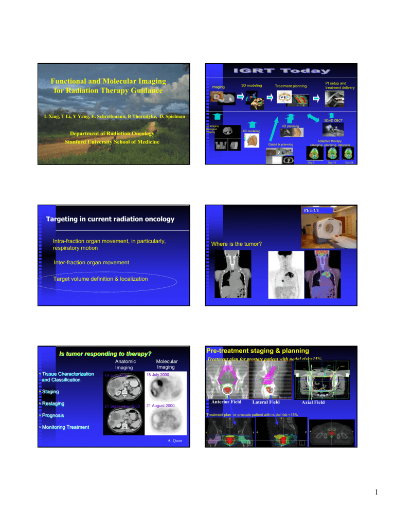
Functional and Molecular Imaging for Radiation Therapy Guidance Imaging 3D modeling Pt setup and treatment delivery Treatment planning L Xing, T Li, Y Yang, E. Schreibmann, B Thorndyke, D. Spielman 3D/4D CBCT 4D imaging Biological imaging Department of Radiation Oncology 4D planning 4D modeling Stanford University School of Medicine Adaptive therapy (imaging, planning, delivery) Gated tx planning Day 0 Day 14 Day 24 PET/CT Targeting in current radiation oncology Intra-fraction organ movement, in particularly, respiratory motion Where is the tumor? Inter-fraction organ movement Target volume definition & localization Pre-treatment staging & planning Is tumor responding to therapy? Anatomic Imaging • Tissue Characterization and Classification Molecular Imaging 19 July 2000 18 July 2000 21 September 2000 21 August 2000 Treatment plan for prostate patient with nodal risk>15% 90% 100% 50% • Staging • Restaging • Prognosis Anterior Field Lateral Field Axial Field Treatment plan for prostate patient with nodal risk <15% • Monitoring Treatment A. Quon 1 Where is the tumor? Where is the boundary of the tumor? Shortcomings of Current Radiation Therapy • Staging and treatment decision-making are based largely on anatomical imaging. • Tumor volume defined on CT/MRI may often be too small or too large. • The whole Rx course takes 5-6 weeks and there is no effective tools to distinguish responders from un-responders. • Detection of recurrence is problematic. What is the biology distribution? • Spatial biology distribution is not considered. Imaging 3D modeling IMRT provides an unprecedented means to produce customized 3D-dose distributions with sub-cm resolution. Pt setup and treatment delivery Treatment planning Integration of radiological imaging techniques allows better patient positioning and dose delivery. 4D imaging Biological imaging 3D/4D CBCT 4D BCRT planning Functional/metabolic imaging modalities are available for noninvasively providing critical needed metabolic and physiological data. 4D modeling Adaptive therapy (imaging, planning, delivery) Day 0 Day 14 Molecular imaging techniques are emerging. Day 24 The Current Imaging Toolbox Method Integration of biological and functional Image. -- Biologically Conformal Radiation Therapy (BCRT) Minimum Detectable Size (φ (φ) Minimum Detected Cells (n) CT 1~2 mm 400,000 MRI 1~2 mm 400,000 MRSI 7 mm (~3mm at 3T) 1,000,000 SPECT 4~6 mm 600,000 PET 3~5 mm 400,000 HFUS <1 mm 100,000 Optics 0.02 mm 1000 ----to truly individualize radiation therapy 2 day4 day1 day8 Luciferase--Transcriptional Reporter Bench-top Small Animal Imaging System: Macroscope hν hν ATP ATP Luciferin Luciferin Luciferase Luciferase ADP ADP ++ Pi Pi Oxyluciferin Oxyluciferin 2+ Mg Mg2+ O O22 Genome Genome Day11 after inoculation Fluorescence Fluorescence Excitation P Maxim, S Gambhir, C Contag, and L Xing, Molecular Imaging. Clinically available molecular/Functional imaging tools Project in Cellular & Molecular Imaging Stanford University Medical Center (C. Contag) ion iss m E Promoter Promoter Luciferase Luciferase Bioluminescence Bioluminescence Genome Genome ion iss Em Substrate & energy Endorectal Coil-Based 3T MR Spectroscopic Imaging for Radiotherapy 3T Endorectal Probe MR Spectroscopic Imaging (MRSI) Functional MRI, DWI/DTI MRSI: monitor the molecular properties of a tumor ER Coil----high SNR MRI/MRSI ER Coil----severely distorts the prostate PET, SPECT PET and PET/CT Topic Characterization of Tissue Example Solitary Pulmonary Nodules Staging Lung Cancer Restaging/Prognosis Lymphoma/Breast Cancer Monitoring Treatment GIST, Breast CA, Lymphoma Emerging Applications XRT planning • Appropriate management decisions starts with accurate staging • PET changes overall management in more than 30% of cases Gambhir, et al 2001 Dizendorf et al, JNM 44, 24-29, 2003 3 Commonly used positron emitters PET/CT for Radiation Therapy • delineate target volume • assess therapeutic response • distinguish recurrent tumor and radiation necrosis Pre-treatment PET/CT/MRI PET/CT/MRI-based tumor delineation Planning & treatment Post-treatment PET/CT/MRI Isotope HalfHalf-life (min.) Production method Application Production Cyclotron Max. range in water (mm) 1.1 11C 20 13N 10 11C-Choline 11B(p,n)11C Cyclotron 1.4 13N ammonia 15O 13C(p,n)13N 2 Cyclotron 1.5 15O water 18F 110 Cyclotron 1.0 FDG, FLT 68Ga 1.1 hr Generator 1.7 82Rb 1.3 Generator 1.7 14N(d,n)15O 19F(p,pn)18F 18O(p,n) 18F Registration & analysis FLT, 11C-choline, 18F-choline, Acetate, F-Dopa, Cu-ATSM, F-MISO, F-EF5… Receptors and peptide-based tracers. Proliferation imaging Buck et al., J Nucl Med, 2003 Post-treatment Functional Image-Guided IMRT • What needs to be done? Reliable imaging tools. Integration---network transfer of functional image files, file format conversion, image fusion/deformable image registration…. Image fusion. Inverse treatment planning. Quality assurance . Clinical study of the efficacy. Pre-treatment Post-treatment 4 A Liver Cancer patient Example: 4D PET Patient setup CTAC (best at expiration) GE 4D PET RPM system GE gated PET Recon selected gates Stanford new 4D PET technique Conventional 3D PET 1 cm 4D planning If bin size = ∆t, then in each respiratory cycle: Bin 1 accumulates events from [0, ∆t] Bin 2 accumulates events from [∆t, 2∆t] Bin 3 accumulates events from [2∆t, 3∆t] . . . Bin N accumulates events from [(N-1)∆t, N∆t] 3D PET --- the lesion in the ungated image is elongated, and mislocalized superiorly by ~1 cm. 16 Ungated Gated at Insp with 1.25 sec Retro. Stacked at Insp 14 12 GET PET – location is right but signal is week. CNR 10 8 R N C 6 4 2 RS 4D PET – location and signal are great☺. 0 -2 3D PET give wrong location and wrong volume 0 5 10 15 20 25 30 35 craniocaudal location (mm) 40 45 50 Functional Image-Guided IMRT RS 4D PET imaging technique sagittal • What needs to be done? coronal Reliable imaging tools. Image fusion. Inverse treatment planning. Quality assurance . Stanford 4D PET image at end-inspiration. The lesion has clearly emerged from the background activity at the end-inspiration location. (B. Thorndyke, E. Schreibmann, A. Koogn, and L. Xing, Med Phys, 2006). Image Registration Automated registration based on control volume(s). CT images Hardware Fusion CT scan Raw CT data 20 min timesaving PET scan Scatter and attenuation correction Raw PET data PET images Schreibmann and Xing, Med. Phys., 2006. ~ 8 min per coach position 5 Head and neck CT, PET, and IMRT treatment plan CT PET PET CT 4D Image Registration Deformable image registration E. Schreibmann and L Xing, IJROBP, 2006 6 Functional Image-Guided IMRT Biological image based inverse treatment planning • What needs to be done? 3 SD 5 SD 7 SD Reliable imaging tools. Image fusion. PET/MRI/MRSI Post-scan data processing Quantify metabolism Inverse treatment planning. Prescription Quality assurance . Beam orientation/profile optimization Fine-tune regional doses Plan review Inverse planning MLC leaf sequencing Biologically Conformal Radiation Therapy IMRT Plan Incorporating MRSI data Biological imaging Spatial distribution of biological parameters Spatially nonuniform conformal dose distribution Target 3 (SD=3) 40% SD=3 95% SD=5 Target 2 (SD=5) 50% SD=7 20% Tissue 40% Target 1 (SD=7) Dose (Gy) L. Xing et al, PMB 47, 3567-3578, 2002 . Prescription for molecular/functional image guided IMRT TCPi = exp[− ρ 0i vi exp(−α i Di + γ i ∆T )] Di = αr 1 1 α ρ Dr − (γ r − γ i )∆T − ln r 0 r αi αi α i α i ρ 0i Functional Image-Guided IMRT • What needs to be done? Reliable imaging tools. Image fusion. Inverse treatment planning. Quality assurance . Yang Y and Xing L, Med. Phys. 2005. 7 Quality Assurance Relationship between the Cho/NAA ratios of the calibration solutions obtained at 9.4 T versus the calibration-solution-filled vials inside the phantom obtained at 1.5 T using a 2D PRESS sequence. S. Hunjan, D. Kim, A. Adalsteinsson, D. Spielman, L. Xing, IJROBP 57, 1159-1173, 2003 S. Hunjan, D. Kim, A. Adalsteinsson, D. Spielman, L. Xing, IJROBP 57, 1159-1173, 2003 4D PET Image Enhancement - Phantom Validation Functional Image-Guided IMRT 3D PET • What needs to be done? Motion direction Motion direction 4D PET (after postacquisition data processing using our new algorithm) 30 Image fusion. Inverse treatment planning. Quality assurance . Ungated Gated with 0.4 sec Gated with 1.0 sec Retro. Stacked 25 Reliable imaging tools. CNR 20 R N C Intensity profiles along the motion direction 15 10 0 -5 -10 A lot of research! B. Thorndyke, E. Schreibmann, A. Koong, L Xing, Med. Phys. 2006 5 0 10 20 30 40 50 superioinferior location (mm) 60 70 80 (B. Thorndyke, E. Schreibmann, A. Koogn, and L. Xing, IJROBP). Summary Functional/molecular imaging is emerging. day1 day4 day8 Next Generation Radiation Therapy Integration of functional & molecular imaging Biologically Conformal IMRT ----to truly individualize Rx Day11 after inoculation Reliable imaging tool, registration, inverse planning, QA, research. P Maxim, S Gambhir, C Contag, and L Xing, Molecular Imaging., 2004 8 ACKNOWLEDGEMENTS Former postdocs- S. Hunjan, J. Lian, … Clinical faculty – A. Koong, K. Goodman, Q. Le, S. Hancock, A. Quon … Physicist – G. Luxton, T. Pawlicki, P. Maxim,…. Funding agency – NIH (1R01 CA98523 & 1R01CA104205) DOD (PC040282 ) 9

