TABLE OF CONTENTS CHAPTER TITLE PAGE
advertisement
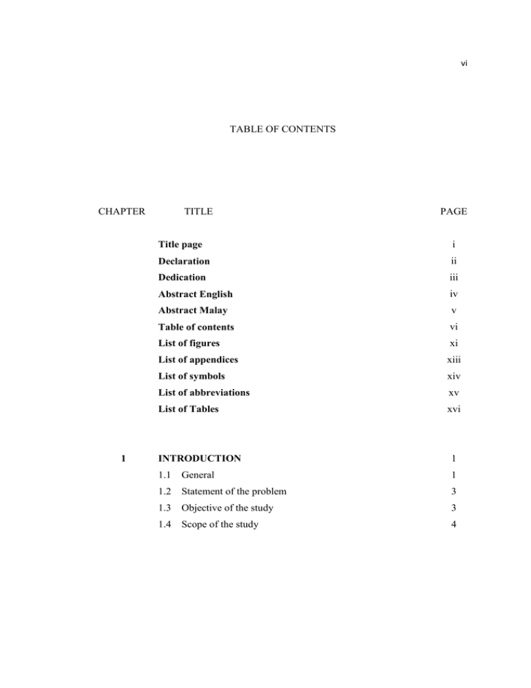
vi TABLE OF CONTENTS CHAPTER 1 TITLE PAGE Title page i Declaration ii Dedication iii Abstract English iv Abstract Malay v Table of contents vi List of figures xi List of appendices xiii List of symbols xiv List of abbreviations xv List of Tables xvi INTRODUCTION 1 1.1 General 1 1.2 Statement of the problem 3 1.3 Objective of the study 3 1.4 Scope of the study 4 vii 2 THEORETICAL BACKGROUND 2.1 Introduction 5 2.2 7 Ordinary differential equation 2.3 Partial differential equation 8 2.3.1. Elliptic equation 9 2.3.2. Parabolic equation 10 2.3.3. Hyperbolic equation 11 2.4 Initial and boundary condition 12 2.4.1. Cauchy condition 13 2.4.2. Dirichlet condition 14 2.4.3. Neumann condition 14 2.5 Concept of Hydraulic 2.6 15 2.5.1. Properties of fluid 15 Flow classification 17 2.6.1. Velocity pattern 17 2.7 Steady and unsteady flow 20 2.8 Basic concept and equations in hydraulics 21 2.8.1. Mass, force, and weight 21 2.8.2. Kinematic viscosity 22 2.8.3. Streamline and stream tubes 23 2.8.4. Dimensionality of a flow field 23 2.8.5. Mass conservation 24 2.8.6. Channel geometric elements 24 2.8.7. Chezy formula 25 2.8.8. Pathline, streakline, and streamline 26 2.8.9. Acceleration 27 2.8.10. Lagrangian and Eulerian system 29 2.8.11. Reynolds number 30 2.8.12. 31 Fluid elements and fluid particles 2.8.13. Control volume 31 viii 2.9 Equation of motion 2.9.1. Flux 33 33 2.9.2. Continuity equation 35 2.9.3. Momentum equation 39 2.9.4. Unsteady term 40 2.9.5. 41 Flux term 2.9.6. resultant force 41 2.9.7. Surface force 42 2.9.8. Body force 42 2.9.9. The force due to internal surface 43 2.10 Reynolds transport theorem 43 2.11 46 Best concepts to understand momentum Force 46 Body force and surface force 47 Unidirectional flow 47 Viscous force 49 Bernoulli equation 49 2.12 Gradually varied flow 49 2.13 2.12.1. Steady gradually varied flow 50 2.12.2. Unsteady gradually varied flow 50 Flow routing 50 2.14 Types of flow routing 50 2.14.1. Hydrologic flow routing 50 2.14.2. Hydraulic flow routing 50 2.15 How to use RivRoute 51 2.15.1. Introduction 51 2.15.2. Input data 51 2.15.3. To run RivRoute 51 2.15.4. External output file 52 2.16 Equation of mass transport 52 ix 2.16.1. Mass transport in flowing water 52 2.16.2. Mass transport equation 56 2.16.3. The last try for predicting of concentration of 57 pollutant 3 METHODOLOGY 58 3.1 Introduction 58 3.2 Assumptions 58 3.3 The governing equations 59 3.4 Continuity equation 59 3.5 Momentum equation 61 3.6 Conservation of energy method 61 3.6.1. To obtain the term 62 3.7 Solving the governing equation 63 3.7.1. Method of solving 63 Finite difference approximation 64 3.8.1. Central difference approximation 64 3.8.2. 64 3.8 Forward difference approximation 3.8.3. Backward difference approximation 3.9 65 Explicit scheme 66 3.10 The difference equation 67 3.11 Continuity equation 68 3.12 Momentum equation 68 3.13 Newton Raphson iteration 69 3.14 Initial condition 70 3.15 Boundary condition 70 3.15.1. Upstream boundary condition 71 3.15.2. Downstream boundary condition 71 3.16 Mass transport 72 x 4 5 3.17 Initial condition 73 3.18 Upstream boundary condition 73 3.19 73 Downstream boundary condition 3.20 Instruction to compute the concentration of pollutant 73 FINDING AND DISCUSSION 75 4.1 Introduction 75 4.2 Graphs discussion 75 CONCLUSION 82 5.1 Introduction 82 5.2 82 Conclusion 5.3 Recommendation for future work 83 Reference 84 Appendix I 87 Appendix II 88 Appendix III 89 Appendix IV 90 xi LIST OF FIGURES FIGURE NO: TITLE PAGE 2-1 The domain of solution for an elliptic PDE 10 2-2 The domain of solution for an parabolic PDE 11 2-3 Trigonometric circle 13 2-4 Compressive force acting on an area 16 2-5 Laminar flow 18 2-6 Sub-critical and super-critical flow 19 2-7 Boundary layers 20 2-8 Lagrangian fluid particle 29 2-9 Eulerian system 30 2-10 Flux definition 34 2-11 Fixed control volume for continuity equation 37 2-12 Fixed control volume for momentum equation 39 2-13 Advective transport 55 3-1 Prismatic channel 59 3-2 Component of energy in prismatic channel 61 3-3 Finite difference approximation 64 3-4 x-t grid of the channel 65 3-5 Normal computation table 66 3-6 Points in upstream/downstream and interior 74 4-1 Concentration and discharge versus time (upstream) 76 4-2 Concentration and discharge versus time (25) 77 xii 4-3 Concentration and discharge versus time (50) 78 4-4 Concentration and discharge versus time (75) 79 4-5 Concentration and discharge versus time (downstream) 80 4-6 3D experimental data 81 xiii LIST OF APPENDICES APPENDIX TITLE PAGE I Input Data Used for RivRoute 87 II Experimental Data 88 III Physical Properties of Work 89 IV Output Data 90 xiv LIST OF SYMBOLS width of channel concentration of pollutant − concentration versus time discharge time coordinate in longitudinal direction Molecular diffusion initial velocity velocity one-dimensional bottom slope of channel the slope of energy grade line gravitational acceleration xv LIST OF ABBREVIATIONS ABBREVIATION WHOLE PHRASE PAGE RAP Remedial action plan 1 CFD Computational fluid dynamic 2 PDE Partial differential equation 7 ODE Ordinary differential equation 7 MOC Method of characteristics 10 Control volume 18 CV xvi LIST OF TABLES NO: 3.1 TITLE Table of Time Derivative and Space Derivative PAGE 67
