TABLE OF CONTENT CHAPTER TITLE PAGE
advertisement
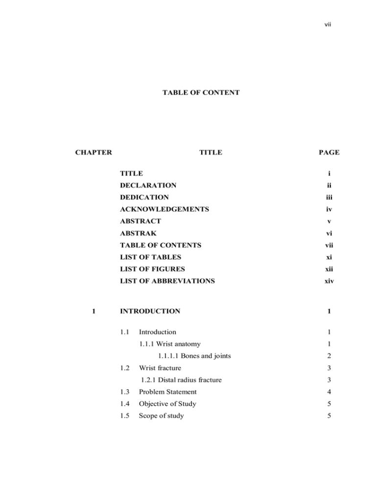
vii TABLE OF CONTENT CHAPTER 1 TITLE PAGE TITLE i DECLARATION ii DEDICATION iii ACKNOWLEDGEMENTS iv ABSTRACT v ABSTRAK vi TABLE OF CONTENTS vii LIST OF TABLES xi LIST OF FIGURES xii LIST OF ABBREVIATIONS xiv INTRODUCTION 1 1.1 Introduction 1 1.1.1 Wrist anatomy 1 1.1.1.1 Bones and joints 1.2 2 Wrist fracture 3 1.2.1 Distal radius fracture 3 1.3 Problem Statement 4 1.4 Objective of Study 5 1.5 Scope of study 5 viii 2 LITERATURE REVIEW 6 2.1 Introduction 6 2.1.1 Classification of intra-articular fracture 6 (1) Intra-articular fracture with displaced dorsal fragment (2) Dorsal split with dorsal dislocation 7 (3) palmar split with palmar dislocaton 8 (4) Complex distal radius fractures with metaphyseal separation (5) Destruction of the articular surface 2.2 9 9 Different studies on fixation methods 10 2.2.1 Clinical Method 10 2.2.1.1 Non-invasive Techniques 11 2.2.1.1.1 Conservative treatment 11 2.2.1.1.2 External Fixation 12 2.2.1.1.3 Pining 13 2.2.1.2 Open surgery 14 (a) Plates 14 (b) Fragment-specific Fixation 15 (c) Volar locking plates 16 2.2.2 Protocol for surgical treatment 17 2.3 Experimental Method 2.3.1 A novel non-bridging external fixator versus volar angular stable plating 2.3.2 Comparing volar with dorsal fixation plates on unstable extra-articular fractures 2.4 7 Computer Simulation Method 18 19 20 22 2.4.1 Biomechanical evaluation of three types of implants 3 METHODOLOGY 22 27 ix 3.1 Introduction 27 3.2 Mimics Software 27 Step 1: Imported the medical data 28 Step 2: Thresholding 29 Step 3: Segmentation density masks 29 Step 4: Region growing 30 Step 5: 3D Reconstruction 31 3.2.1 32 Constructed of fractured bone 3.3 Implant Design 3.3.1 Introduction of Solidworks Software 35 3.3.2 Designing the implants 36 Simulation of surgical fixation 37 3.5 Introduction to MSC.Marc Software 39 3.4 4 35 3.5.1 Analysing the three fixation methods 40 3.5.2 Applying the loads 41 RESULTS AND DISCUSSION 43 4.1 Introduction 43 4.2 Axial-loads results 44 4.2.1 Displacement 44 4.2.2 Von-Mises Stress 46 4.3 Bending results 4.4 49 4.3.1 Displacement 49 4.3.2 Von-Mises Stress 51 Torsional results 53 4.4.1 Displacement 54 4.4.2 Von-Mises Stress 55 4.5 Overviewing of three three fixation methods 58 4.6 Validation of study 60 4.6.1 Surgical validation 60 4.6.2 Experimental validation 60 x 5 DISCUSSION AND RECOMMENDATION 62 5.1 Discussion 62 5.2 63 Recommendations REFERENCES 64 xi LIST OF TABLES TABLE NO. TITLE PAGE 4.1 Maximum displacement (mm) and maximum von Mises stress (MPa) values of the bone around the screws of all three groups under the applied loads 47 4.2 Maximum displacement (mm) and maximum von Mises stress (MPa) values of the bone around the screws of all three groups under the bending loads 52 4.3 Maximum displacement (mm) and maximum von Mises stress (MPa) values of the bone around the screws of all three groups under the torsional loads 57 xii TABLE OF FIGURES FIGURE NO. TITLE 1.1 Distal and proximal rows of carpal bones 2 2.1 CT-based classification of comminuted intra-articular 7 PAGE fractures of the distal radius. Type I: intra-articular fracture with displaced dorso-ulnar fragment 2.2 Type II: dorsal split with dorsal dislocation 8 2.3 Type III: palmar split with palmar dislocation 8 2.4 Type IV: complex distal radius fractures with 9 metaphyseal separation 2.5 Type V: destruction of the articular surface 10 2.6 Schematic drawing of a monolateral external fixator 13 with double ball joints after application to the radial aspect of the second metacarpal and diaphysis of the radius: the distal ball joint is centred between the capitate (C) and lunate bone (L) (intraoperatively by identification with a bone elevator under image intensification, lower part of the image) to allow for mobilisation of the fixator. xiii 2.7 Typical placement of two T-pins for fixation a distal 14 radius fracture is shown in this posterior-anterior radiograph. The surgeon has inserted two T-pins from the radio styloid to stable fracture fixation. The surgeon has inserted two T-pins from the radio styloid to stable fracture fixation 2.8 A fragment-specific wrist fixation system 15 2.9 A 31-year-old woman with reverse Barton fracture 16 fixed by volar locking plate 2.1O The southern Sweden treatment protocol for DRF 18 when selecting different treatments the patient’s age and demands 2.11 Experimental test with isolated radius placed of 19 custom-made compensator to applied ratio (60-40%) of the forces transferred to scaphoid and lunata fragments. (A) Non-bridging external fixation method. (B) Volar locking fixation method 2.12 (A)The LDRS 2.4-mm intermediate and styloid plates. 21 (B)The LDRS 2.4-mm volar plate. (C)The LDRS 2.4-mm volar and styloid plates. (D) The 3.5-mm stainless steel T plate. 2.13 Finite element of different surgical methods. (A) T shape single volar plate meshing model. (B) Meshing model of double-palates fixation method. (C) The modified double-plating (MDP) meshing model 23 xiv 2.14 Loading conditions for model. Axial loading bending 24 and torsion are indicated with arrows. The axial loading was applied in the middle of the upper radius surface. The bending force was applied on the volar side of radius. Torsion is applied on both sides of the radius representing the external rotating force 2.15 (A) Average total displacement of the fracture site 25 under 50 N axial compression, 2 N-m bending and 2 N-m torsion loads. (B) Maximum displacement of the fracture site under 50 N axial compression, 2 N-m bending and 2 N-m torsion loads 2.16 (A) Maximum von Mises stress value for bone in 26 single, DP, and MDP models under 50 N axial compression, 2 N-m bending and 2 N-m torsional loads. (B) Maximum von Mises stress value of T plate in single, DP, and MDP models under 50 N axial compression, 2 N-m bending and 2 N-m torsional loads 3.1 CT scan image for using in mimic 28 3.2 The top and side views for radius bone that 29 Thresholding by the white color triangular to separate the radius bone 3.3 The side view of region growing that shown in pink 30 color 3.4 The process of smoothing (A, B and C) to achieve 31 radius bone 3.5 The measured guide lines for cutting (A) Approximately 10 mm(10.44 mm) from the from articular surface. (B) About 15° (14.81°) volar wedge 33 xv 3.6 The simulated three segments unstable intra-articular 33 fracture (AO 23-C2.1 fracture). The circle shows the cut with the curve tool 3.7 (A) The scaphoid segment cleaned meshes. 34 (B) The lunate segment cleaned meshes. (C) The distal part of the radius cleaned meshes (all segment related to the cortical parts only) 3.8 (A) Intermediate dorsal LDRS 2.4 mm plate. (B) Volar 37 T-shape LDRS 2.4 mm plate. (C) I-shape Styloid LDRS 2.4 mm plate 3.9 Fixed all the meshes around the screws on both cortical 38 and cancellous parts of bone 3.1O Fixed all the interfaced meshing part between all 39 cancellous and cortical and screws. (The red parts show the interfaced parts) 3.11 Defined the young’s modulus, Poisson’s ratio and 40 contact parts for each part (that showed in collared parts) 3.12 Axial loading that applied on scaphoid and lunate 42 regions base on each percentage and tilt angle, bending load that exerted on simulated bone on volar side of the radius and the torsion applied of the radius part of the bone 4.1 Model rigidity under axial compressive load 45 4.2 Maximum displacement of the bone around the screws 45 under the 10 N, 25 N, 50N, and 100 N loads xvi 4.3 Maximum von-Mises stress under the 10 N, 25 N, 50N 46 and 100 N loads 4.4 Maximum von-Mises stress of the bone around the 47 screws under the 10 N, 25 N, 50N, and 100 N loads 4.5 The contour plots of displacement for three groups of 48 fixations under applied 100 N axial load 4.6 The mean maximum displacement under bending loads 50 (1 N-m, 1.5 N-m, 2 N-m) 4.7 The maximum displacement around the screws under 50 applied bending loads (1 N-m, 1.5 N-m, 2 N-m) 4.8 The maximum von-Mises stress under applied bending 51 loads (1 N-m, 1.5 N-m, 2 N-m) 4.9 The maximum von-Mises stress around the screws 51 under applied bending loads (1 N-m, 1.5 N-m and 2 N-m) 4.1O The contour plots of displacement for three groups of 53 fixations under applied 2 N bending load 4.11 The mean maximum displacement under torsion loads 54 (1.5 N-m, 2 N-m, 2.5 N-m) 4.12 The maximum displacement around the screws under 55 applied torsion loads (1.5 N-m, 2 N-m, 2.5 N-m) 4.13 The maximum von-Mises stress under applied bending 56 loads (1.5 N-m, 2 N-m and 2.5 N-m) 4.14 The maximum von Mises stress around the screws under applied torsion loads (1.5 N-m, 2 N-m and 2.5 N-m) 56 xvii 4.15 The contour plots of displacement for three groups of 58 fixations under applied 2 N torsional load 4.16 (A) Average total displacement of the fracture site under the 100 N axial compression, 2 N-m bending and 2.5 N-m torsional loads. The total displacement was averaged from the displacement of the nodes on the fracture site. (B) Maximum von Mises stress value for bone in three groups of fixations under 100 N compression load, 2 N-m bending and 2.5 N-m torsional loads 59 xviii LIST OF ABBREVIATIONS 2D - Two Dimensional 3D - Three Dimensional CAD - Computer-Aided design CT - Computerized Tomography DRFs - Distal Radius Fractures DP - Double Plating FEA - Finite Element Analysis HU - Hounsfield Scale LCPS - Locking Compression Plate System LCPS - Locking Compression Plate System LDRS - Locking Distal Radius System MDP - Modified Double Plating MRI - Magnetic Resonance Imager
